Chapter 4: APIC-EM and the EasyQoS Application
The Application Policy Infrastructure Controller—Enterprise Module (APIC-EM) is Cisco’s enterprise SDN controller. EasyQoS is one of several applications which run on APIC-EM. The following sections discuss how to access APIC-EM, declaratively express QoS policies within the EasyQoS application, and then deploy those QoS policies to groups of network infrastructure devices.
Logging Into APIC-EM
APIC-EM provides a web-based GUI for configuring and monitoring the base APIC-EM functionality as well as the applications that reside upon it.
- Note: APIC-EM also includes an extensive set of northbound REST-based APIs for configuring and monitoring APIC-EM functionality and the applications that reside upon it. This version of the APIC-EM EasyQoS Design Guide does not cover the northbound REST-based APIs. Future versions may include a discussion of the northbound APIs.
In order to access the APIC-EM login page, the network operator must launch a web browser and open an HTTPS connection to the IP address or fully qualified domain name of the APIC-EM server. An example of the login page is shown in the figure below.
- APIC-EM Login Screen

Upon entering the proper login credentials (username and password) and clicking the Log In button, the network operator will be taken to the APIC-EM Home page, as shown below.
- APIC-EM Home Page
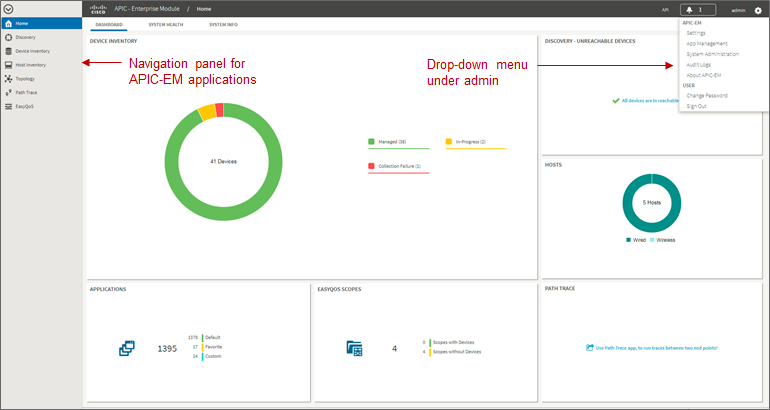
APIC-EM supports both integration with an external AAA server via the RADIUS protocol, as well as an Internal Users database locally administered on the APIC-EM server. Both are accessed from Settings within the drop-down menu that appears when clicking “admin” in the upper right-hand corner of any APIC-EM page, as shown in the figure above.
The expandable navigation panel on the left-side of any APIC-EM page displays the various applications (or functions) available within APIC-EM. The following four applications (or functions) provided by the APIC-EM controller are not part of the EasyQoS application itself but are discussed within this document, because they provide necessary functionality for the EasyQoS application to operate.
- Network Device Discovery
- Device Inventory
- Host Inventory
- Topology
This document does not discuss the IWAN, Network Plug and Play, Integrity Verification, Remote Troubleshooter, Cisco Active Advisor, or Cisco Wide Area Bonjour applications, because they do not directly provide functionality that is required for the EasyQoS application. The Path Trace application is briefly mentioned at the end of the *APIC-EM and the EasyQoS Application* chapter.
Network Device Discovery
In order to apply QoS Policies to network devices within the EasyQoS application, network devices must first be discovered, added the APIC-EM device inventory, and managed by APIC-EM. Hence, the network operator must first perform a Discovery in order to discover network devices and place them into the Device Inventory database. Clicking the Discovery icon with the expandable panel on left-side of any APIC-EM page takes the network operator to the Discovery page. An example is shown in the following figure.
- APIC-EM Discovery Page
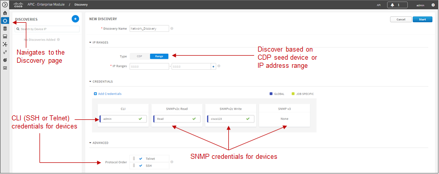
The Discovery page allows the network operator to create Discovery jobs based on either a Cisco Discovery Protocol (CDP) seed device or an IP address range. The Discovery process requires SNMP credentials (v2c, or v3) and CLI credentials (SSH or Telnet) to be entered. The network operator must ensure that CLI credentials—including an enable password—have been previously configured on the network device and that the device is network reachable from APIC-EM.
SNMP and CLI credentials for devices can be created and stored via Settings within the drop-down menu that appears when clicking “admin” in the upper right-hand corner of any APIC-EM page. The following screen shot shows an example of where the CLI credentials are configured within APIC-EM.
- Adding CLI Credentials to APIC-EM
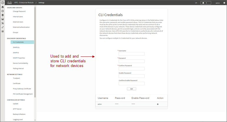
SNMP credentials can be added similarly. The saved credentials can then be referenced within the Discovery process.
APIC-EM release 1.3 added a Device Controllability feature. This feature allowed APIC-EM to configure the SNMP credentials onto network infrastructure devices—via the CLI interface. APIC-EM release 1.4 extended the Device Controllability feature by allowing APIC-EM to selectively configure both SNMP credentials and/or IP Device Tracking (IPDT) onto network infrastructure devices—via the CLI interface. Both of these functions can save time by not requiring the network operator to manually access each network infrastructure device and configure the SNMP credentials or IPDT. The following figure shows the screen that appears when selecting Device Controllability.
- Device Controllability Feature
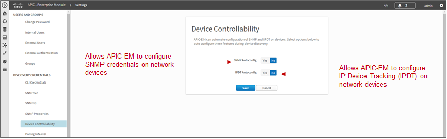
If the SNMP Autoconfig functionality within the Device Controllability feature is disabled (which is the default setting), the network operator must ensure that SNMP access is configured on each network device and that each device is SNMP reachable from APIC-EM.
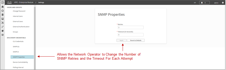
The SNMP Properties page can be used to modify the number of SNMP retries and the timeout between each attempt. The network operator may find it useful to modify the default settings if some network devices occasionally experience SNMP timeouts when APIC-EM attempts to synchronize its Device Inventory database with those devices. An example of the SNMP Properties page is shown below.
- SNMP Properties
APIC-EM release 1.4 and higher allows the polling interval by which APIC-EM synchronizes the Device Inventory database with each network device to be configurable via the Polling Interval Settings page. An example is shown in the figure below.
- Polling Interval
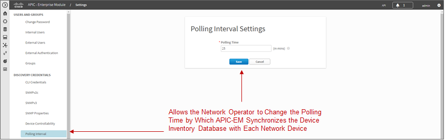
The default setting of 25 minutes is also the minimum polling interval. The polling interval can be extended up once every 24 hours if desired.
Device Inventory
Only after network devices have been discovered will those devices be added the APIC-EM Device Inventory database and managed by APIC-EM. Clicking the Device Inventory icon within the expandable panel on left-side of any APIC-EM page takes the network operator to the Device Inventory page. An example is shown in the following figure.
- APIC-EM Device Inventory Page
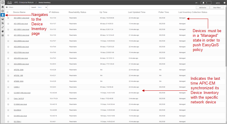
As mentioned previously, devices must be in a Managed state in order to provision EasyQoS policy. APIC-EM periodically (approximately every 25 minutes by default) synchronizes the Device Inventory database with each network device. However, the polling interval can be modified, as discussed in the *Network Device Discovery* section. If changes to the configuration of a particular network device have been made either via CLI or via management platforms such as Prime Infrastructure, it is recommended that you wait until APIC-EM has re-synchronized with the device, in order to ensure the configuration changes have been identified by APIC-EM, before applying any changes to QoS policy through EasyQoS. Alternatively, you can manually synchronize an individual device by selecting it within the device inventory and clicking the Resync button within the menu that appears. An example is shown in the figure below.
- Manual Resync of a Network Device
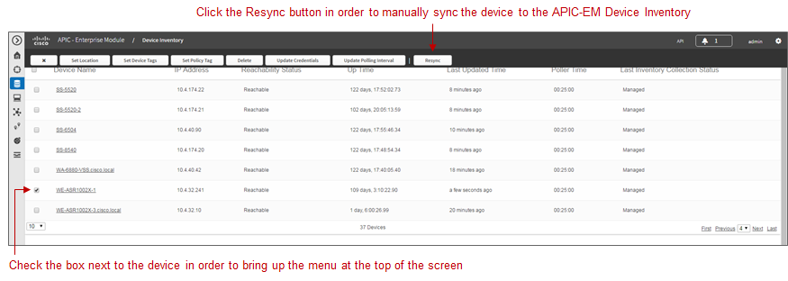
The manual resync feature, which is available as of APIC-EM release 1.4 and higher, allows the network operator to set a longer polling interval if desired – yet still re-sync individual devices when necessary. A longer polling interval may ease the amount of processing and therefore lower CPU utilization of APIC-EM for larger deployments, especially when changes to network infrastructure devices occur infrequently.
An example of why a device would need to be resynchronized would be adding or changing a WAN service provider profile (SPP) tag manually via the CLI to a Cisco ISR or ASR WAN interface. APIC-EM would have to resync with the ISR or ASR in order to be aware of the updated WAN SPP tag first, in order to apply the appropriate QoS policy to the WAN interface.
The location feature allows the network operator to assign a geographic location to a device or set of devices. This affects how the network is viewed within the Topology page. For small networks, displaying all devices in the network within a single Topology page may be acceptable. However, as the number of devices grows, the network operator may wish to view devices based upon their geographic location——such as all devices per branch location, per campus location, per campus building, etc.
The network operator can assign a location to a device or group of devices by selecting the device or devices within the Device Inventory page and then clicking the Set Location button, shown in the figure above. This brings up a popup screen, as shown in the figure below.
- Location Popup Screen
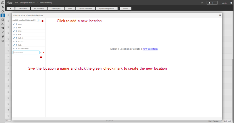
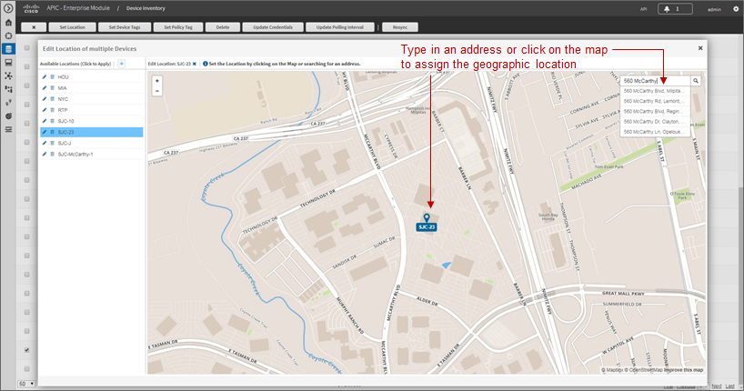
In order to create a new location, click the blue + adjacent to Available Locations. This will bring up a new blank box field below the existing locations. The network operator must give the new location a name and click the green checkmark to create the location. Location names should not contain blank spaces. When the new location is created, a new screen will appear, prompting the network operator to either type in an address corresponding to the new location or click a geographic location within the displayed map. The network operator can zoom in to a specific geographic location within the map if necessary. An example is shown in the following figure.
- Setting the Address of the New Location
Host Inventory
Cisco Device Endpoints
APIC-EM also discovers certain Cisco hardware device endpoints which are then included within Static and Dynamic QoS policies provisioned to network infrastructure devices. These hardware endpoints include the following:
- Cisco IP phones
- Cisco TelePresence devices
- Cisco video conferencing endpoints
- Cisco video surveillance cameras
APIC-EM makes use of CDP running on Catalyst switches in order to discover these hardware endpoints. EasyQoS uses the IP addresses of the hardware endpoints collected through CDP information, along with the knowledge of which Catalyst switch and switch port the endpoint is connected to—in order to pre-populate access control entries (ACEs) within classification & marking access control lists (ACLs) for Static and Dynamic QoS on switching devices. In order for this functionality to operate, CDP must be enabled on the Catalyst switch ports that connect to hardware endpoint devices. By default CDP is enabled on Cisco Catalyst switch ports.
The Cisco hardware endpoint devices themselves must also support CDP. The CDP information provided by the hardware endpoint must also include its IP address. If the IP address is not included, APIC-EM will not know which switch port to populate with ACE entries.
- Note: Older versions of Cisco TelePresence code may not support the sending of IP addresses within CDP when in a VLAN configuration—such as when a Voice VLAN is configured. Such systems may require an upgrade to TC7.3.6, CE8.0.2, or CE8.1.1 or higher in order for these devices to be statically populated within the correct ingress classification & marking ACLs when deploying EasyQoS. Please refer to Cisco defect CSCuy71139 for details.
Discovered Cisco endpoint devices are populated within the Host Inventory database within APIC-EM. These can be displayed by clicking the Host Inventory icon with the expandable panel on left-side of any APIC-EM page. An example of the Host Inventory page is shown in the following figure.
- APIC-EM Host Inventory Page
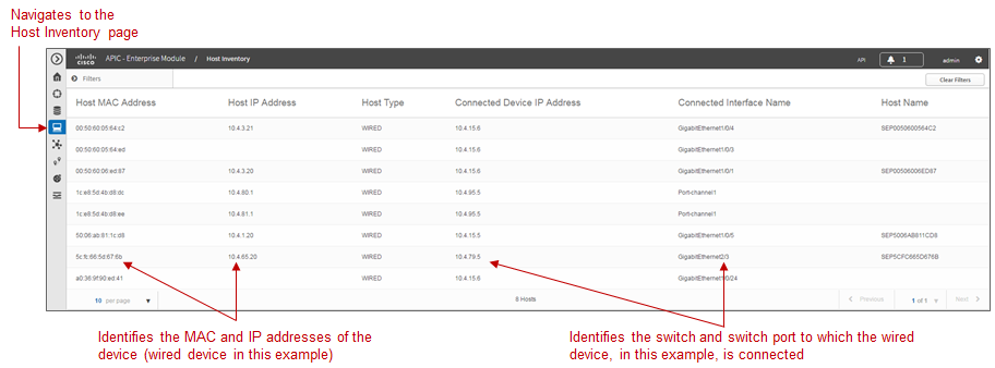
For wired Cisco device endpoints, after the endpoint information is collected, APIC-EM provisions ACE entries into the ACLs configured for Static QoS corresponding to the ingress classification & marking policy deployed across all access-edge ports on the switch to which the device is connected. This is discussed in detail in the *Cisco Device Endpoints* section of the *Campus LAN Static QoS Design* chapter. If Dynamic QoS is enabled, EasyQoS will also push ACE entries into the Dynamic ACL policy shells corresponding to the dynamic ingress classification & marking policy for the specific switch port as well. Dynamic QoS is discussed in detail within the *Dynamic QoS Design* chapter.
There are no equivalent ACE entries generated for wireless devices with the current EasyQoS solution. This is because the AireOS wireless LAN controller (WLC) EasyQoS ingress classification & marking policy uses Cisco Application Visibility and Control (AVC) profiles, rather than Layer 2-4 ACLs.
Topology
After network infrastructure devices have been discovered, the network operator can view the network via the Topology page. The Topology page is accessed by clicking the Topology icon within the expandable panel on left-side of any APIC-EM page. If devices have been assigned locations, the initial view of the Topology page will be a map, as shown in the following figure.
- APIC-EM Top-Level Map
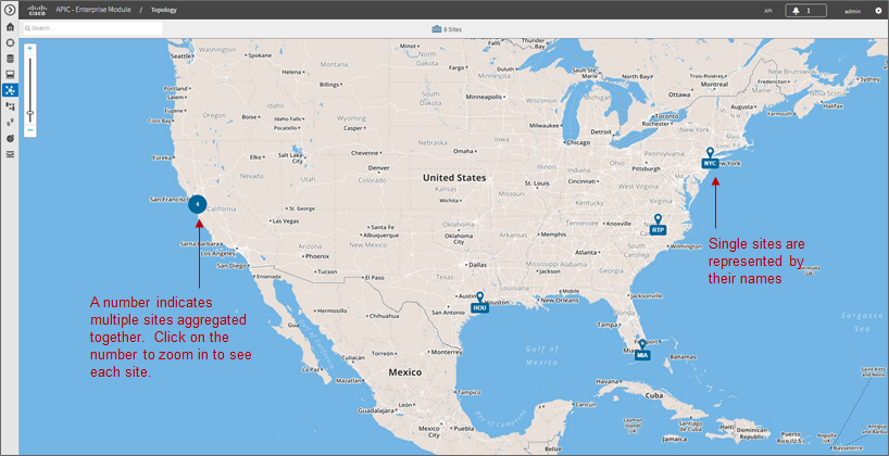
Individual sites are identified by their location names. Locations that are geographically close are aggregated together and represented by a number. Clicking the number will zoom the map in closer to reveal each site, as shown in the following figure.
- Zooming in to Reveal Aggregated Sites
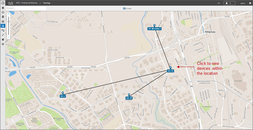
Finally, by clicking the name of an individual location, the network operator can display the topology of the devices within the site. An example is shown in the following figure.
- Displaying the Topology of Devices within a Location
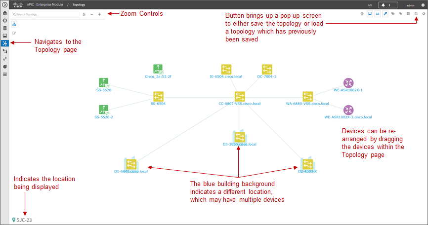
APIC-EM automatically discovers the relationship between devices and connects them together within the Topology page. Individual devices or groups of devices can be re-positioned by dragging them around within the page and by zooming-in and zooming-out as needed. When the network operator has arranged the devices as desired, he/she can save the layout via the Save or Load Topology icon in the upper right corner of the Topology page. This can be loaded in the future when visiting the Topology page, so that the network operator doesn’t have to re-arrange the devices upon every visit to the Topology page.
Clicking a device will bring up a side window with additional detail on the device—including the role of the device within the network—as shown in the figure below.
- Selecting the Role of a Device from Within the Topology Page
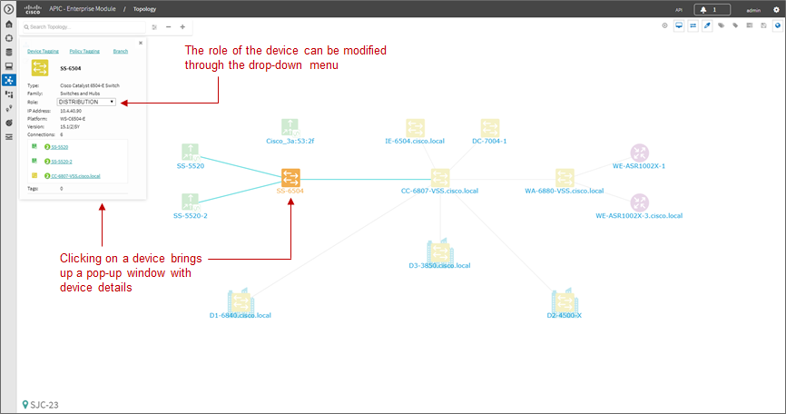
Each discovered network infrastructure device is automatically categorized into one of the following roles:
- Core
- Distribution
- Access
- Border Router
- Unknown
The Core, Distribution, and Access roles apply to Catalyst switches. The Access role also applies to WLC platforms. The Border Router role applies only to Cisco ISRs and ASRs. The network operator should verify that the particular device selected has been characterized with the correct role, in order to ensure the correct QoS policy is applied to the device by the EasyQoS application. This applies primarily to Catalyst switches. If necessary, the network operator can change the role within the side window. The policy applied to Catalyst switches based upon their role is discussed in the *Campus LAN Static QoS Design* chapter.
EasyQoS Application
The Discovery, Device Inventory, Host Inventory, and Topology functions discussed in the previous sections are not part of the EasyQoS application. However, they were discussed because the functionality they provide is necessary for the EasyQoS application to operate. This section shifts the discussion to the specific functionality within the EasyQoS application itself.
The EasyQoS application is accessed by clicking the EasyQoS icon within the expandable panel on left-side of any APIC-EM page. An example is shown in the following figure.
- APIC-EM EasyQoS
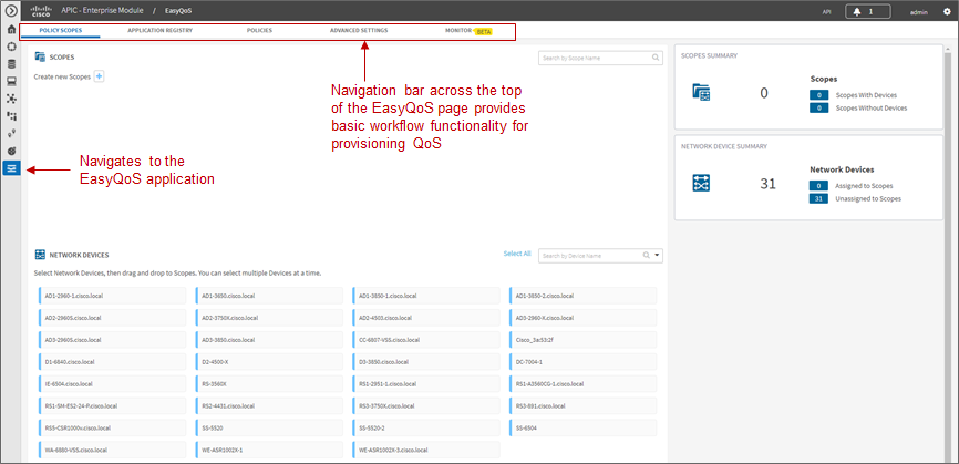
As shown in the figure above, the EasyQoS application has several tabs that appear as a bar across the top of the page.
- Policy Scopes
- Application Registry
- Policies
- Advanced Settings
- Monitoring (Beta)
The tabs are intended to roughly guide the network operator through something similar to a basic workflow for deploying QoS policy. Therefore, it is recommended that you access the tabs in order (from left to right) when deploying QoS policy, although the network operator is free to access the tabs in any order. Each of these tabs will be discussed in separate sections.
Policy Scopes
The network operator is by default automatically taken to the first tab—Policy Scopes—when clicking the EasyQoS application icon within the expandable panel on left-side of any APIC-EM page.
The first step to deploying QoS policy through EasyQoS is to create one or more policy scopes. Policy scopes are simply a way of grouping one or more network devices together in order to apply QoS policy to the group all at once, rather than having to individually apply QoS policy to one network device at a time.
The network operator can define a single policy scope for all of the network devices under his/her administrative control. Alternatively, the network operator is free to define multiple policy scopes—each of which contains one or more network devices. Either way, EasyQoS will deploy the appropriate QoS policy to each device, based upon the network topology, the role of the device within the network, and the application-level business intent expressed by the network operator. Up to 2,000 devices can be configured in a single policy scope as of APIC-EM version 1.3 and higher.
In order to create a new policy scope, the network operator can click the + next to Create New Scopes on the upper left side of the Policy Scopes tab. An empty box representing the new policy scope name will appear. The network operator will be prompted to give the new policy scope a name and click the green check mark in order to create it. An example is shown in the following figure.
- Creating a New Policy Scope
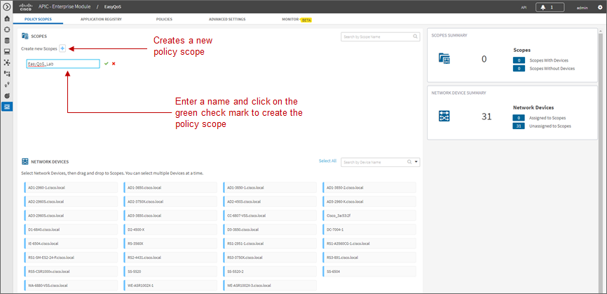
- Note: The Policy Scope name cannot include any blank spaces. Use either an underscore, dash, or single word for the Policy Scope name.
When a new policy scope is created, it contains no network devices. In order to add network devices to a policy scope, the network operator must drag-and-drop one of the available devices within the Network Devices panel into the policy scope. A network device can be a member of only one policy scope at a given time. Only network devices that have been Discovered and added to the Device Inventory of APIC-EM will appear within the Network Devices panel, as shown in the figure above.
After a device has been dragged-and-dropped into a policy scope, it will no longer appear within the Network Devices panel. Instead, it will appear within the right-hand panel within the display when the network operator clicks on the policy scope. An example is shown in the figure below.
- Displaying Network Devices within a Policy Scope
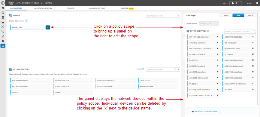
Individual network devices can be deleted from the policy scope by clicking the “x” next to the network device name. The Save button must be clicked in order to save the changes. Devices removed from a policy scope automatically appear again within the Network Devices panel underneath the Scopes panel. The network operator can also delete the entire policy scope by clicking the Delete button.
After the desired number of policy scope(s) are created and the desired network devices have been moved into the policy scope(s), the network operator can click the Application Registry tab.
Application Registry
The second step in deploying QoS policy through EasyQoS is to access the Application Registry in order to select Favorite applications and to create Custom applications. The Application Registry serves as a common repository of applications known to APIC-EM via the NBAR taxonomy, Favorite applications, and Custom applications. It can be leveraged by various APIC-EM applications such as EasyQoS and IWAN. An example of the Application Registry is shown in the figure below:
- Application Registry
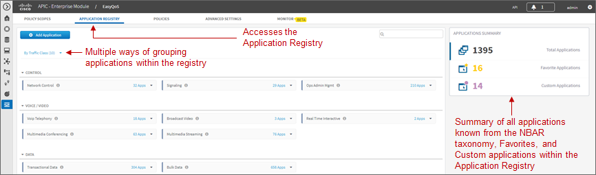
Applications can be grouped in multiple ways when viewing them within the left-panel of the Application Registry as follows:
- Applications—This lists all applications (both from the NBAR taxonomy and Custom applications) alphabetically.
- Application Groups—This lists all applications based on the NBAR application category attribute to which the applications belong.
- Traffic Class—This lists all applications based on the NBAR traffic-class attribute to which the applications belong.
The panel on the right provides a summary of all the 1300+ applications known via the NBAR taxonomy as of NBAR2 Protocol Pack 27.0.0, all Favorite applications, and all Custom applications currently known and/or configured within APIC-EM.
Favorite Applications
The concept of Favorite Applications has been added to EasyQoS to address the issue that some platforms have limited ability to support applications. For instance, Cisco AireOS WLCs currently can support only 32 applications per AVC profile. Likewise, some older Catalyst switch platforms have limited TCAM space, hence can only support a limited number of ACE entries within the ingress classification & marking ACLs deployed to these devices by EasyQoS.
By selecting an application as a Favorite, the network operator declares a preference for including that application within QoS policies provisioned by EasyQoS, over other applications. When EasyQoS creates QoS policies, it will select applications that have been marked as Favorites for inclusion within the policies before the remainder of the applications within the NBAR taxonomy. Note that by default Custom applications are automatically marked as Favorite applications when they are created.
Applications are selected as Favorites by clicking the star next to the name of the application. Clicking the star causes it to turn yellow, indicating application has been selected as a favorite. An example is shown in the figure below.
- Selecting Favorite Applications
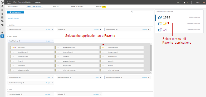
The list of Favorite applications is global to the APIC-EM EasyQoS deployment—meaning that Favorites are the same across all Policy Scopes. The list of Favorite applications can be displayed by clicking Favorite Applications in the panel on the right side of the Application Registry.
Changing the Traffic-Class of an Application
EasyQoS within APIC-EM release 1.5 and higher allows the network operator to change the traffic-class to which an application belongs. By default, all 1300+ applications known to the NBAR2 taxonomy are assigned a traffic-class, based on IETF RFC 4594 guidelines. However, the network operator may sometimes wish to change this. For example it may be desired to put both the audio and video components of a collaboration session into the same traffic-class, rather than have the audio media in the VoIP Telephony traffic-class and the video media in the Multimedia Conferencing traffic class. The network operator can change this by selecting the application within the Application Registry. This will bring up a panel on the right-hand side of screen as shown in the figure below.
- Selecting an Application within the Application Registry
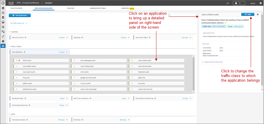
Clicking the Edit button will change the right-hand panel, allowing the network operator to select the desired traffic-class of the application from the drop-down menu. When the network operator is satisfied with the new traffic-class, he/she can click the Save button in the upper right corner of the panel in order to save the changes to the application.
- Changing the Traffic-Class of an Application Example
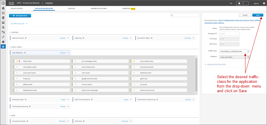
Changing the traffic-class of an application will modify the EasyQoS ingress classification & marking policy for that particular application. The effects on ASR and ISR router configuration of changing the traffic-class of an application are discussed in the *Changing the Traffic-Class of Applications on ASR and ISR Platforms* section of the *WAN and Branch Static QoS Design* chapter. The effects on Catalyst switch configuration are discussed in the *Ingress Classification & Marking Policies* section of the *Campus LAN Static QoS Design* chapter.
Custom Applications
The Application Registry is also where the network operator can create Custom applications. Although AVC/NBAR currently identifies approximately 1300+ applications, organizations sometimes develop their own internal applications, which may not be recognized by AVC/NBAR. In order to identify and provide the proper QoS treatment for these applications across the network infrastructure, the network operator can create a Custom application for each of them.
Custom applications are added by clicking the Add Application button within the Application Registry page. The right-hand panel of the page will change, allowing the network operator to add the application based upon a URL or a Server IP/Port range. An example is shown in the following figure.
- Custom Application Based on a URL
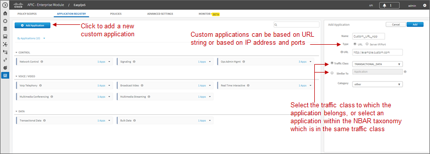
In the example above, the Custom application is based on a URL. For an EasyQoS Custom application based on a URL, the network operator must provide the following information:
- A name by which APIC-EM will know the application
- The URL string to which the application is matched against within AVC/NBAR policies
- The traffic class to which the application belongs
- Note: EasyQoS within APIC-EM release 1.5 and higher does not do verification of the URL string to ensure it is properly formatted.
If the network operator does not know to which traffic class the Custom application should belong, he/she can simply select the Similar To check box and use the drop-down menu to select one of the applications known to EasyQoS via the NBAR taxonomy that has similar characteristics. By similar characteristics, we mean that the NBAR traffic-class and category attributes assigned to that similar application will also be assigned to the Custom application.
Custom applications that are based on URLs are not capable of being deployed on Catalyst switch platforms. They are only deployed onto ISR and ASR platforms that implement policy-maps that contain “match protocol attribute” statements. This is because the traffic-class attribute must be programmed into the Custom application, and the traffic-class attribute requires a “match protocol attribute traffic-class” statement to be configured within the policy-map. An example of the policy configuration for a Custom application that is based on a URL is shown in the *Custom Applications on ASR and ISR Platforms* section in the *WAN and Branch Static QoS Design* chapter.
Alternatively, a Custom application can be based upon one or more IP addresses (or address ranges) and one or more IP, TCP, and/or UDP ports (or port ranges). An example using multiple IP addresses and port ranges is shown in the following figure.
- Custom Application Based on Server IP Address and Ports
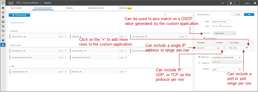
For an EasyQoS Custom application based on a server IP addresses and ports, the network operator needs to provide the following information:
- A name by which APIC-EM will know the application
- A DSCP value (optional). This field is used to match on a DSCP value generated by the Custom application within the QoS policy generated by EasyQoS.
- Port Classifiers (optional), which include one or more IP addresses or IP address ranges, along with one or more protocols (IP, TCP, UDP, or TCP/UDP), and one or more ports or port ranges.
- The traffic class to which the application belongs
The example in the figure above demonstrates the use of the subnet mask field—set to 24 bits (10.0.1.0/24) in the first row of the Port Classifiers—to include a full subnet as a destination IP address range. Likewise, the range (3000-3010) in the first row of the Port Classifiers shows how to include a range of ports (UDP ports in this example—based on the Protocol setting for the particular row). This IP address or address range as well as port or port range refers to a destination—also referred to as the producer. Additional rows can be added to include more individual IP addresses or IP address ranges, as well as more ports or port ranges to the Custom application.
As with URL-based Custom applications, if the network operator does not know to which traffic class the Custom application should belong, he/she can simply select the Similar To check box and use the drop-down menu to select one of the applications known to EasyQoS via the NBAR taxonomy that has similar characteristics. By similar characteristics, we mean that the NBAR traffic-class and category attributes assigned to that similar application will also be assigned to the Custom application.
Custom applications that are based on server (destination) IP addresses and ports are capable of being deployed on both Catalyst switch platforms and ASR or ISR platforms. For Catalyst switch platforms, the server (destination) IP address or address range, ports, and/or DSCP fields are translated into one or more ACEs that are populated within the ACL corresponding to the traffic-class to which the Custom application belongs. An example of this is shown in the *Access-Control Lists* section in the *Campus LAN Static QoS Design* chapter.
For more complex applications, a source IP address or address range as well as a source port or port range can be added to the Custom Application. This is referred to as adding a Consumer to the application. Adding a Consumer is discussed in the *Policies* section below.
Advanced Settings
With APIC-EM release 1.4, configuration of SP Profiles and Dynamic QoS was moved under the Advanced Settings tab. Additionally, a new feature, Bandwidth (BW) Profiles, was added. APIC-EM release 1.5 renamed Bandwidth Profiles to Queuing Profiles and extended this by allowing the network operator to change the default DSCP marking of traffic-classes. The following sections discuss Queuing Profiles and SP Profiles. Dynamic QoS is discussed in a separate *Dynamic QoS* section.
Queuing Profiles
Queuing Profiles provide a means for the network operator to customize the following:
- The amount of bandwidth allocated for each of the 12 traffic-classes provisioned by EasyQoS
- The DSCP marking to be applied to traffic associated with each of the 12 traffic-classes
EasyQoS includes a default Queuing Profile named CVD_Queuing_Profile. Allocation of the bandwidth across the traffic-classes and the DSCP marking associated with each traffic-class within the default Queuing Profile is fixed, as shown in the following figure.
- Default Queuing Profile
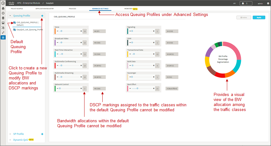
In order to modify the bandwidth allocations or DSCP markings, the network operator must create a new custom Queuing Profile by clicking the blue “+” next to Queuing Profile on the left panel of the Advanced Settings screen, as shown in the figure above. This will bring up a new Queuing Profile screen similar to the one in the following figure.
- Creating a Custom Queuing Profile – BW Allocation Example
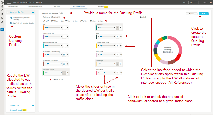
The network operator must first provide a unique name for the custom Queuing Profile.
Bandwidth Allocations
Bandwidth allocations for each of the traffic-classes can be set independently for each of the interface speeds shown in the figure above. This is accomplished by highlighting the link speed (100 Gbps, 10/40 Gbps, 1 Gbps, 100 Mbps, 10 Mbps, or 1 Mbps) and adjusting the bandwidth allocations for each traffic-class. For example, the network operator can set bandwidth allocations for 1 Gbps access ports (ports connected to end-user devices) differently from 10 Gbps uplink ports (ports connected to other network infrastructure devices) within the same custom Queuing Profile. For link speeds that are between the values listed, the bandwidth allocations for the next lower link speed apply. Alternatively, the network operator can choose to apply the same bandwidth allocations for each traffic-class to all link speeds by selecting the Apply to all References checkbox.
Each of the 12 traffic-classes in the figure above have a slider that can be used to adjust the bandwidth allocated for the traffic-class. Alternatively, the network operator can simply type in the desired bandwidth in the box adjacent to the slider. The bandwidth allocated for each traffic-class represents the percentage of the total bandwidth. The sum of the bandwidth allocations for all of the traffic-classes must always equal 100 percent.
- Note: As of APIC-EM release 1.6.0, the network operator can change the default 1% bandwidth allocation of the Scavenger traffic-class within a custom Queuing Profile within the EasyQoS GUI. However, changing the bandwidth allocation of the Scavenger traffic-class will have no effect on the actual bandwidth allocation provisioned by EasyQoS to network devices for the Scavenger traffic-class. Further, since the bandwidth allocations within the custom Queuing Profile of the EasyQoS GUI must total 100%, the percentage bandwidth allocations actually provisioned by EasyQoS for the remaining traffic-classes will not match what is shown within the custom Queuing Profile. For further details, refer to Cisco defect CSCvg74117.
In order to adjust the bandwidth allocated to a given traffic-class, the network operator must first ensure the traffic-class is unlocked. The lock icon in each traffic-class locks and unlocks the bandwidth allocation for the traffic-class. Adjusting the bandwidth allocation for one of the unlocked traffic-classes automatically causes the bandwidth in the remaining unlocked traffic-classes to be re-distributed such that the sum of the bandwidth allocation for all traffic-classes is always 100 percent.
One method of specifically setting the bandwidth allocation for all of the traffic-classes would be as follows:
- Unlock all of the traffic-classes
- Select the first traffic-class, set the bandwidth allocation percentage for that traffic class, and lock the traffic-class
- Repeat for the remaining traffic-classes
- The final traffic-class will have the remaining bandwidth percentage not allocated to the other traffic-classes
- Note: The Voice, Broadcast Video, and Real-Time Interactive traffic-classes are considered to be priority traffic within Queuing Profiles. These traffic-classes may be mapped to priority queues on platforms. If the amount of bandwidth allocated to these three traffic-classes exceeds 33%, the network operator will receive a warning indicating that this is not recommended because it could cause bandwidth starvation of non-priority queues.
At any point, the network operator can click the Reset to CVD icon within the screen to reset the bandwidth allocations for the traffic-classes back to their default values.
Bandwidth settings within Queuing Profiles are used to calculate the bandwidth rates used in the commands which configure the various hardware queues in the queuing policies provisioned to each of the supported Catalyst and Nexus switching platforms. Switch platforms typically have only 4 or 8 hardware queues. Bandwidth allocation percentages from the Queuing Profile traffic-classes that are mapped into a specific hardware queue, are summed to obtain the rate configured within the queuing policy. The actual configuration is also dependent upon the specific platform and/or line card. More specifically, the configuration depends upon the number of hardware queues supported by the platform or line card, the number of priority queues supported by the platform or line card, and whether the priority queues are bounded or unbounded. Bounded priority queues have a maximum configured traffic rate (often implemented through a policer), and unbounded priority queues can use as much bandwidth as needed. When priority queues are supported, the bandwidth percentages from the Queuing Profile are adjusted from “bandwidth percentages” to “bandwidth remaining percentages” when configured into policy maps on MQC or C3PL platforms or egress queuing commands on MQC platforms. “Bandwidth remaining percentage” is the amount of bandwidth remaining after accounting for the bandwidth used in priority queues.
Bandwidth allocation settings within Queuing Profiles are also used to calculate the bandwidth rates used in the commands that configure the various software queues in the egress queuing policy provisioned to ASR and ISR router platforms. Bandwidth allocation settings within Queuing Profiles apply only to ISR and ASR interfaces that are not part of a WAN SP Profile. In other words, they apply only to interfaces which implement the WAN edge queuing policy discussed in the *WAN Edge Egress Queuing Policy* section in the *WAN and Branch Static QoS Design* chapter. Because router platforms only implement egress queuing policies, and because these policies are implemented in software, each of the 12 traffic-classes within the Queuing Profile maps to an egress queue (a class-map entry within a policy-map). Because the WAN edge queuing policy implements three low-latency queues (three priority queues), the remaining bandwidth percentages from the bandwidth allocation settings within the Queuing Profile are adjusted from “bandwidth percentages” to “bandwidth remaining percentages” when configured into the policy maps.
DSCP Markings
- Note: Caution should be used when changing the default DSCP marking of traffic-classes from the Cisco recommended 12-class QoS model. Such changes could result in a less than optimal QoS implementation unless the network operator is highly knowledgeable in QoS design and implementation. This feature is only for customers with advanced knowledge of QoS.
DSCP markings for each traffic-class can be modified by highlighting DSCP instead of one of the link speeds (100 Gbps, 10/40 Gbps, 1 Gbps, 100 Mbps, 10 Mbps, or 1 Mbps), as shown in the figure below.
- Creating a Custom Queuing Profile – DSCP Markings Example
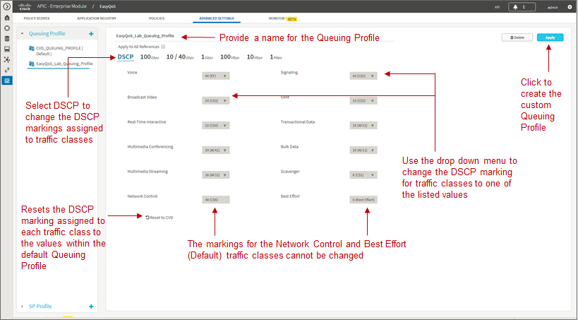
DSCP markings for the Best Effort (Default) and Network Control traffic-classes cannot be modified. EasyQoS does not provision a class-map entry for Network Control traffic within the ingress classification & marking policy applied to access-layer switches. Network Control traffic is not expected to be seen inbound on a switch port connected to an end-user device. Because no class-map entry exists for Network Control traffic within the ingress classification & marking policy, no policy action, such as setting the DSCP marking of the traffic can be taken. Therefore EasyQoS does not allow modification of the DSCP marking of Network Control traffic. By default, Network Control traffic is considered to be marked with DSCP 48 (CS6).
For the remaining 10 traffic-classes, the network operator can modify the DSCP marking applied to traffic matching the particular traffic-class. This is accomplished through the drop-down menu adjacent to the traffic-class, as shown in the figure above. The drop-down menu will only display DSCP marking values which have not been assigned to another traffic-class already. This is because EasyQoS always deploys a 12-class QoS model. Each of the traffic-classes within the 12-class model must have a policy-action which sets the DSCP value of the matching traffic to a unique value. In other words, EasyQoS will not allow two different traffic-classes within the ingress classification & marking policy-map to have policy-actions which map to the same DSCP value. If the DSCP marking which you wish to assign a traffic-class is already being used by another traffic-class, you must first change the other traffic-class to mark to a different DSCP value. Selectable DCSP values range from 0 to 63, excluding DSCP 0 (Best Effort) and DSCP 48 (CS6).
In the figure above, Broadcast Video traffic has been marked to CS3 and Signaling traffic has been marked to CS5, as specified in IETF RFC 4594, purely as an example of changing traffic-classes, not as a best-practice. Cisco recommends a modification to RFC 4594 in that Signaling traffic is marked to CS3 and Broadcast Video is marked to CS5. The default setting for call signaling within Cisco Unified Communications Manager is set to CS3.
The DSCP markings for each traffic-class are independent of the BW allocations applied to interface speeds. In other words, the DSCP markings are applied to all interface speeds for supported devices within the policy scope. At any point, the network operator can click the Reset to CVD icon within the screen to reset the DSCP markings for the traffic-classes back to their default values, which are the recommended settings for the Cisco RFC 4594-based 12-class QoS model.
When the network operator is satisfied with the bandwidth allocations for each of the interface speeds and the DSCP markings within the custom Queuing Profile, he/she can click the Create button in the upper right side of the screen to create and save the custom Queuing Profile.
Queuing Profile Support by Platform
Bandwidth allocation selections and DSCP markings within custom Queuing Profiles are not supported by all interfaces and all platforms. The following table summarizes the platform support as of APIC-EM release 1.6.
- Platform Support for BW Allocation and DSCP Marking Within Custom Queuing Profiles
| Platform | BW Allocation | DSCP Marking |
|---|---|---|
| Catalyst 6K Series with Sup2T and Catalyst 6880 & 6840 Series | Ingress and Egress queues on line cards/supervisors with a 2P6Q4T queuing structure are supported (BW allocations are modified) by custom BW allocations. All other line cards are not supported by custom BW allocations within Queuing Profiles. Non-supported line cards/supervisors implement EasyQoS default BW allocations within queuing structures. | Custom DSCP markings for traffic-classes are supported (DSCP markings are modified) for line cards/supervisors which support DSCP to queue mapping. These include the following: 2P6Q4T ingress and egress queuing is supported by the following line cards: C6800-8P10G, C6800-8P10G-XL C6800-16P10G, C6800-16P10G-XL C6800-32P10G, C6800-32P10G-XL 8Q4T ingress queuing is supported by the following line cards: VS-S2T-10G, VS-S2T-10G-XL with Gigabit Ethernet ports disabled WS-X6908-10G-2T, WS-X6908-10G-2TXL 1P7Q4T egress queuing is supported by the following line cards: WS-X6908-10G-2T and WS-X6908-10G-2TXL VS-S2T-10G and VS-S2T-10G-XL with Gigabit Ethernet ports disabled For all other line cards and queuing structures the EasyQoS default DSCP markings are implemented for traffic-classes. |
| Catalyst 6K Series with Sup-720 | Custom BW allocations are not supported (BW allocations are not modified). Line cards implement EasyQoS default BW allocations within queuing structures. | Custom DSCP markings for traffic-classes are not supported (DSCP markings are not modified) for any line cards/supervisors. EasyQoS default DSCP markings are implemented for traffic-classes. |
| Catalyst 3850 and 3650 Series | Custom BW allocations are supported (BW allocations are modified) on the 2P6Q3T egress queuing structures. | Custom DSCP markings for traffic-classes are supported (DSCP markings are modified) for these platforms. |
| Catalyst 4K Series with Sup-7E, 7LE, 8E, and 8LE and Catalyst 4500-X Series | Custom BW allocations are supported (BW allocations are modified) on the 1P7Q1T egress queuing structures. | Custom DSCP markings for traffic-classes are supported (DSCP markings are modified) for these platforms. |
| Catalyst 2960-C, 2960-CX, 2960-S, 2960-X, 2060-XR, 3560-C, 3560-CX, 3560-X, and 3750-X Series, as well as the SM-ES2 Series EtherSwitch module | Custom BW allocations are supported (BW allocations are modified) on the 1P3Q3T egress queuing structures. Custom BW allocations are not supported (BW allocations are not modified) on the ingress queuing structures of those platforms which support ingress queuing. | Custom DSCP markings for traffic-classes are not supported (DSCP markings are not modified) for these platforms. EasyQoS default DSCP markings are implemented for traffic-classes. |
| Nexus 7K Series | Custom BW allocations are not supported (BW allocations are not modified). Modules/supervisors implement EasyQoS default BW allocations within queuing structures. | Custom DSCP markings for traffic-classes are not supported (DSCP markings are not modified) for any modules/supervisors. EasyQoS default DSCP markings are implemented for traffic-classes. |
| ISR 800, ISR G2, ISR 4K, ASR 1K, and CSR 1000v Routers | Custom BW allocations are supported (BW allocations are modified) only on interfaces which implement the LAN Edge egress queuing policy. BW allocations within custom Queuing Profiles do not apply (BW allocations are not modified) on interfaces that implement a WAN SP Profile. Custom BW allocations for WAN SP Profiles are configured under Custom SP Profiles. | Custom DSCP markings are supported (DSCP markings are modified) on interfaces which implement the LAN Edge egress queuing policy. Changing the DSCP marking of a traffic-class will not alter the re-marking of the traffic-class as it enters a service-provider WAN when implementing a WAN SP Profile. Custom DSCP markings for WAN SP Profiles are configured under Custom SP Profiles. However, changing the DSCP marking of a traffic-class will alter the re-marking of the traffic-class as it exits a service-provider WAN and re-enters the network, when implementing a WAN SP Profile. This is because the ingress classification & marking policy is applied to traffic re-entering the network from the service provider WAN. |
| AireOS WLC Platforms | Custom BW allocations do not apply to AireOS WLC platforms. | Custom DSCP markings are supported (DSCP markings are modified) by changing the DSCP marking of applications belonging to the respective traffic-class. This is done within the AVC Profile. |
Changing the DSCP marking of a traffic-class will modify the EasyQoS egress queuing policy for that particular traffic-class. The effects on ASR and ISR routers of changing the DSCP marking of a traffic-class are discussed in the *Changing the DSCP Markings of Traffic-Classes on ASR and ISR Platforms through Custom Queuing Profiles* section in the *WAN and Branch Static QoS Design* chapter. The effects on Catalyst switches are discussed in the *Ingress Classification & Marking Policies* section of the *Campus LAN Static QoS Design* chapter. Finally, the effects on wireless LAN controller platforms are discussed in the *QoS Trust Boundaries and Policy Enforcement Points* section of the *WLAN QoS Design* chapter.
SP Profile
The configuration of custom SPPs is an optional step that is dependent upon the following two questions:
- Is a managed-service WAN implemented on any interface of any ISR or ASR router within the scope of the policy to be deployed?
- If there is a managed-service WAN, does the service match one of the four default SP profiles provided by EasyQoS?
The four default SP profiles provided by EasyQoS can be viewed by clicking SP Profile within the Advanced Settings tab and then highlighting one of the four default profiles as shown in the following figure:
- Default SP Profiles Provided by EasyQoS
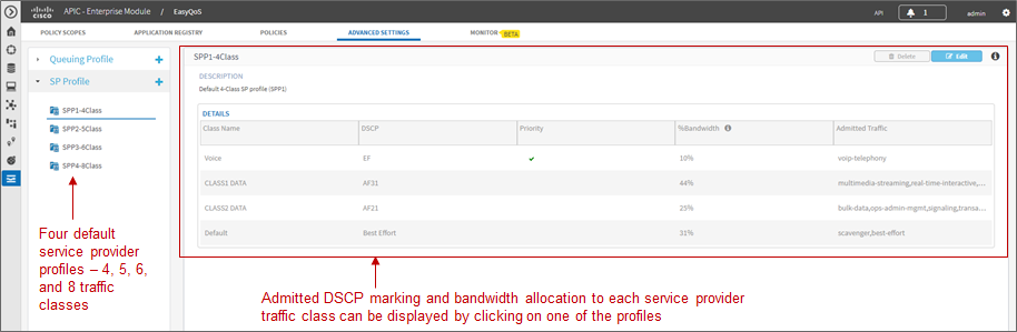
The network operator can view the bandwidth allocations and the admitted DSCP markings for each of the service provider traffic-classes for each of the profiles by simply clicking one of the four default SP profiles.
- Note: If the QoS policy has previously been deployed, and if the selected default SP Profile has been deployed to devices within the policy scope, the devices and interfaces will be displayed within a panel at the bottom of the screen.
If the network operator determines that none of the four default SP profiles matches a managed-service WAN deployed on an interface on any of the devices within the policy scope, he/she can create a custom SP profile by clicking the blue + next to SP Profile in the upper left corner of the page. This will bring up a page similar to the following:
- Creating a Custom SP Profile
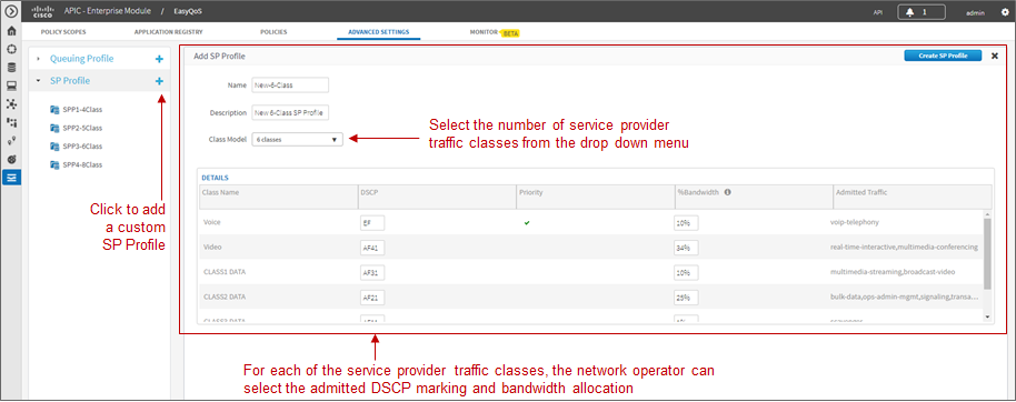
Custom service provider profiles are based on the four default SP profile templates—meaning that custom SP profiles can only have 4, 5, 6, or 8 traffic-classes. The network operator must first select the number of classes in the custom SP profile through the drop-down menu next to Class Model. This will change the Details panel below it to reflect the number of traffic-classes in the model. The network operator can change the admitted DSCP marking to the service provider traffic-class or accept the default value. Likewise, the network operator can change the amount of bandwidth allocation to the particular service provider traffic-class, or accept the default value.
The Voice traffic-class is the only traffic-class that is mapped to a low-latency queue (LLQ), otherwise known as a priority queue. Because the Voice traffic-class is a priority queue, the remaining bandwidth allocations are technically bandwidth remaining allocations—which must total to 100%—regardless of the amount of bandwidth allocation provisioned to the Voice traffic-class.
When the network operator is satisfied with the admitted DSCP markings and bandwidth allocations for the service provider traffic-classes, he/she can click the Create SP Profile button in the upper right corner of the page in order to create the custom SP Profile.
The application of service provider profiles—regardless of whether they are one of the four default SP profiles, or a custom SP profile—to WAN interfaces is done automatically by APIC-EM. It is based on the network operator having previously configured a specific tag within the description of the WAN interface connected to a managed service WAN. This is discussed in detail within the *Service Provider Managed-Service WAN QoS Design* chapter.
Policies
The next step to deploying QoS policy through EasyQoS is to access the Policies tab in order to create a policy under a scope.
Excluding Interfaces
Before creating a policy, the network operator may wish to exclude certain interfaces on switch and router platforms from the policy. This may be done in situations where different QoS policies or configurations are required on the same router or switch platform. Because a router or switch platform can only be part of a single EasyQoS scope at any given time—and therefore have only one EasyQoS policy applied to it at a time—excluding interfaces provides additional functionality for the network operator to manually configure the desired QoS policy on those interfaces. Alternatively, interfaces may be excluded when the QoS policy provisioned by EasyQoS doesn’t specifically meet the requirements of certain interfaces.
APIC-EM release 1.5 and higher provides the ability to exclude interfaces from the QoS policy provisioned by EasyQoS. Interfaces can be excluded by clicking the gear symbol to the right of the name of each switch or router platform within a policy scope, as shown in the figure below.
- Excluding One or More Interfaces from EasyQoS Policy
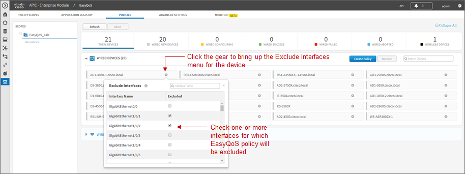
This will bring up a drop-down menu listing the interfaces on the particular switch or router platform. The network operator can exclude interfaces simply by checking the Excluded box next to the name of each interface listed within the drop-down menu.
- Note: If a policy has already been applied to one or more devices, the network operator can still go into those devices and exclude interfaces. However, the policy has to be re-applied in order for the changes to take effect.
For port-channel configurations, if one physical interface which is a member of the port-channel is excluded, then all other physical interfaces that are members of the same port-channel should be excluded as well. QoS policy across the physical interfaces that are members of a port-channel configuration should be consistent.
Creating Policies
When the network operator is done excluding interfaces on router and switch platforms within the policy scope, he/she can then begin creating the policy itself. An example is shown in the figure below.
- Creating a Policy Within a Policy Scope
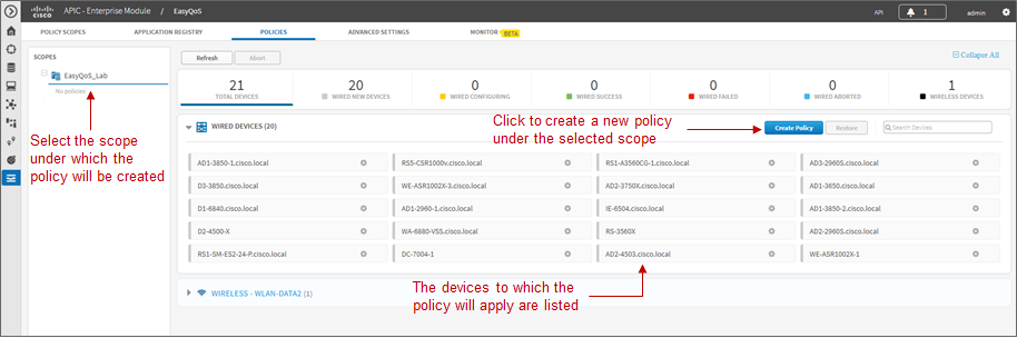
Policies are created and applied per policy scope. Therefore policies only affect those devices that are part of the particular scope to which the policy is applied.
Clicking the Create Policy button brings up the screen used to create, configure, view, and apply the policy. An example is shown in the figure below.
- Configuring EasyQoS Policy
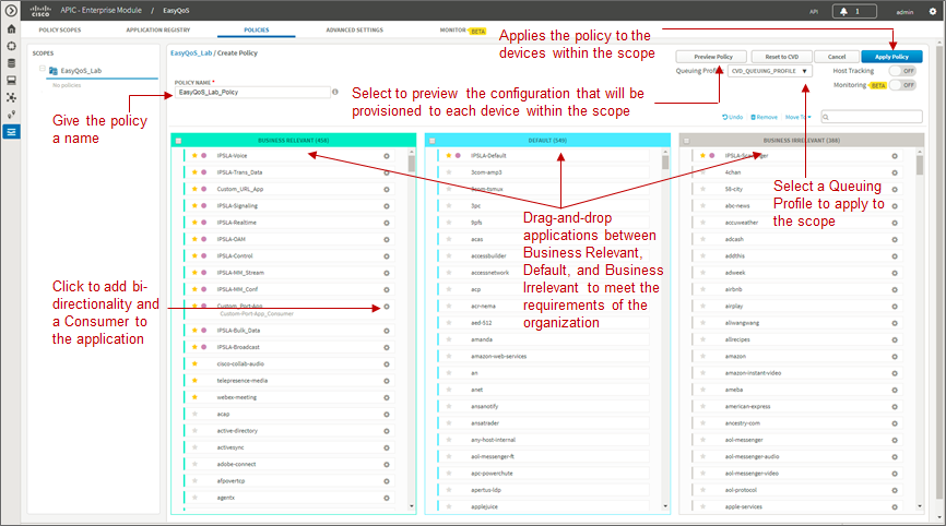
It is mandatory to name each QoS policy. The purpose of the policy is as follows:
- To capture the application-level business intent of the network operator
- To apply a Queuing Profile to the policy
- To transform the business intent and Queuing Profile into network device QoS configuration for each device within the policy scope
- To apply the configuration to the devices within the policy scope
- Finally, to inform the network operator of the status of applying the policy to each device within the policy scope
The application-level business intent of the network operator is captured by dragging-and-dropping individual applications known via the Application Registry between the three business-relevance attribute values of Business Relevant, Default, and Business Irrelevant. All 1300+ applications known within the NBAR taxonomy have default settings for the business-relevance attribute. The network operator can simply choose to accept these default values, or customize as many applications as needed to meet the business requirements of the organization.
The network operator must also select the business-relevance attribute of Custom applications—either Business Relevant, Default, or Business Irrelevant, by dragging-and-dropping Custom applications into the appropriate grouping. By default, custom applications are Unassigned when they are created.
Changing the business-relevance of an application changes its QoS treatment across the network, as discussed in the *Mapping Business-Relevance to QoS Treatments* section of the *Strategic QoS Policy* chapter.
- Note: If a policy is applied before changing the business-relevance of the Custom application, the Custom application will not be included within the policy. However, because applications with a business-relevance of Default do not have any actual configuration generated on network devices for those applications, the Custom applications will in effect be treated with a business-relevance of Default across the network infrastructure.
As of APIC-EM 1.5 and higher, the network operator can choose to apply a custom Queuing Profile to a policy. The creation of Queuing Profiles was discussed in the Queuing Profiles section above. The network operator can choose to accept the default CVD_Queuing_Profile, or choose a custom Queuing Profile from the drop-down menu.
The application-level business intent and Queuing Profile is then transformed by APIC-EM EasyQoS into QoS configuration for each network device within the policy scope covered by the policy. The configurations are based upon best practice recommendations for QoS configuration, compiled through years of CVD guidance.
Consumers, Producers, and Bi-Directionality
The Policies page is where the network operator can choose to make the application bi-directional, as well as add a Consumer (a source IP address or IP address range, and/or source port or port range). This is done by clicking the icon next to the name of the application, which brings up a pop-up screen to edit the details of the application. An example using the Custom application discussed earlier is shown below.
- Adding Bi-Directionality and a Consumer to an Application
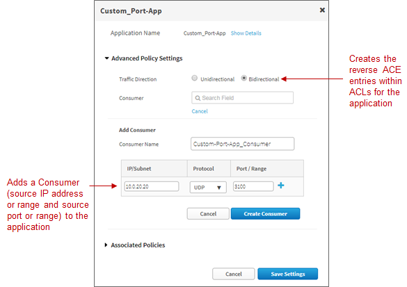
All Ingress classification & marking policies implemented on Catalyst switches use ACE entries within ACLs. Ingress classification & marking policies for Custom applications implemented on ISR and ASR platforms also use ACE entries within ACLs. These ACE entries are, by default, unidirectional. The bi-directional feature is intended to ensure that return traffic from an application is classified and marked correctly when the destination (the Producer) is not within a data center or on a server where the switch port to which the server is connected can be configured to trust the DSCP markings of traffic from the server.
- Note: On ISR and ASR platforms, ingress classification and marking policies involving any of the 1300+ applications known to the NBAR taxonomy are handled by the AVC/NBAR engine and are bi-directional.
As mentioned in the previous paragraph, ingress classification and marking policies implemented on Catalyst switches, as well as custom applications implemented on ISR and ASR platforms use ACE entries within ACLs. These ACE entries by default only specify a destination IP address or range of IP addresses, as well as a destination port or port range. The source is by default “any” device. In order to specify a source IP address or IP address range as well as a source port or port range, a Consumer is created and added to the application. This can be for a Custom application or for any of the 1300+ applications know to the NBAR taxonomy. The network operator accomplishes this by simply giving the Consumer a name, specifying a source IP address or IP address range, specifying whether the transport layer protocol is UDP or TCP, specifying a port or port range, and clicking the Create Consumer button. This, along with the choice for bi-directionality must be saved before closing the Edit Application Details pop-up screen.
The effects on ASR and ISR router configuration of adding bi-directionality and a Consumer are discussed in the *Custom Applications on ASR and ISR Platforms* section of the *Branch and WAN Static QoS Design* chapter. The effects on Catalyst switch platforms is discussed in the *Access-Control Lists* section of the *Campus LAN Static QoS Design* chapter.
Reset to CVD
As applications are dragged-and-dropped between the Business Relevant, Default, and Business Irrelevant groupings within a given policy, the network operator may lose track of their original default settings. Likewise as bi-directionality and consumers are added to individual applications within a policy, the network operator may lose track of which applications have been set for bi-directionality and/or have consumers added. The network operator has the ability to reset the applications back to their original business-relevance attribute setting, and to remove bi-directionality and consumers within a given policy, by clicking the Reset to CVD button. Note that the selection of Favorites is system-wide (that is, across policies and policy scopes) and therefore unaffected by the Reset to CVD button.
Policy Preview
Before applying the configuration, the network operator can optionally choose to preview the policy. This option is enabled by selecting the Preview Policy button within a policy. When Preview Policy is selected, an additional panel will appear as shown in the following figure.
- Generating a Policy Preview for a Device
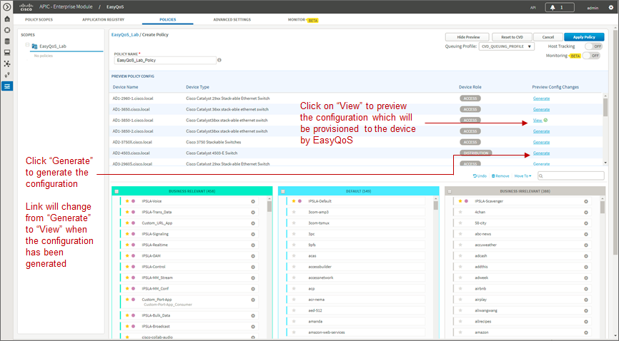
The Preview Policy Config panel allows the network operator to generate the actual commands that will be provisioned to each device by EasyQoS. This is done by clicking the Generate link adjacent to the specific device. The Generate link will change to View when the configuration has been generated. Clicking the View link will bring up a pop-up window in which the configuration commands will appear. The configuration commands can then be viewed by scrolling up and down within the panel. An example is shown in the figure below.
- Displaying the Preview Configuration
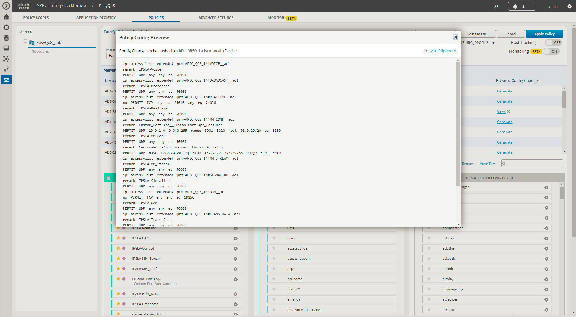
The preview policy option can be useful in uncovering potential errors in applying policy—such as an unsupported line card within a Catalyst 6500 Series switch for instance—before the policy is applied. The network operator can then take remedial actions, such as removing the device from the policy scope, or removing the line card from the switch—before applying the policy. Because the actual configurations that are provisioned by EasyQoS to each device are generated, this may also improve the time taken to deploy the policy to all of the devices within the scope, as well.
Scheduling a Policy
When the network operator is satisfied with the policy, he/she can click the Apply Policy button in the upper right corner of the policy screen. This will bring up a pop-up window in which the network operator can immediately apply the policy, or schedule the policy to be applied at a future date and time. An example is shown in the following figure.
- Scheduling a Policy
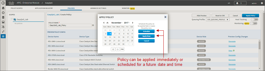
APIC-EM release 1.4 and higher supports the ability to schedule a policy at a future time and date. Scheduled policies are applied only once—meaning that a policy cannot be scheduled to reoccur every day, hour, etc.
When a policy is scheduled to be run at a future date and/or time, the policy screen will appear similar to the example in the figure below.
- Policy Scheduled for a Future Date and/or Time
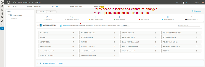
The policy scope to which the policy will be applied is locked when a policy is scheduled to be applied at a future date and/or time. This means the policy scope cannot be modified. The scheduled date and/or time cannot be modified once the policy has been scheduled. The network operator can only cancel the policy by clicking the Cancel button at the top of the policy screen, as shown in the figure above. Cancelling a scheduled policy will result in the policy being deleted if this is a new policy. If the policy is an update to an existing policy, then the updates will be lost if the scheduled policy is cancelled. EasyQoS provides a pop-up screen warning of the potential loss of the policy data and prompting for a confirmation before cancelling a scheduled policy.
Policy Status
When a policy is applied, EasyQoS provides the status of the policy on each device—as the policy is being applied. Initially each device will appear with a gray bar next to it—indicating that no policy is applied (if this is a new device to EasyQoS with no policy). A yellow bar next to a device indicates that policy is currently being configured onto the device. Finally, a green bar next to the device indicates that the policy has successfully been provisioned onto the device. An example of the policy being applied to devices within the scope is shown in the following figure.
- Policy Status
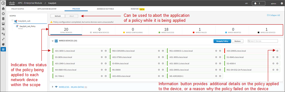
Clicking the information button next to each network device brings up a popup window with Device Details. The Device Details window serves two purposes—depending upon whether the policy was successfully applied to the device or not. If the policy was successfully applied to the device, clicking the information button next to the device will display the applications which were deployed in the policy provisioned to the device—based upon the business relevance of each application. An example is shown in the figure below.
- Device Details when Policy is Successfully Applied to a Device
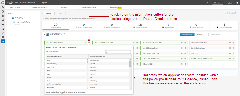
Only applications which are business-relevant or business-irrelevant are configured into policies on switch, router, and AireOS WLC platforms. Applications with default business relevance receive best effort treatment, and therefore do not show up within the policy provisioned to network devices.
If the policy failed to be applied to the device, clicking the information button next to the device may display a reason why the policy failed. An example is shown in the figure below.
- Device Details when Policy Fails to be Applied to a Device
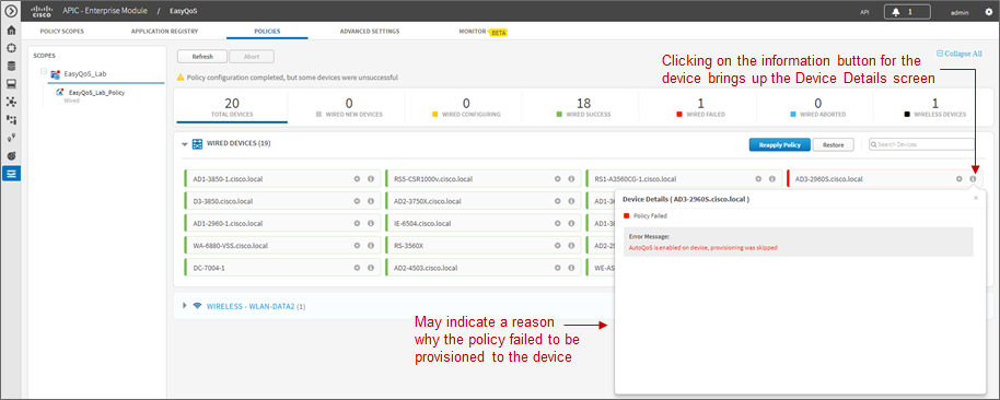
In the example above, the information within the Device Details screen indicates that policy was skipped because AutoQoS is currently enabled on the switch platform. EasyQoS currently does not support provisioning QoS policy to devices with AutoQoS enabled. In this case, the network operator can manually remove AutoQoS configuration and resync the device before attempting to re-apply policy. Alternatively, the network operator can simply remove the device from the policy scope.
After a policy has finished being applied to devices within the policy scope, clicking the name of the policy within the left-hand panel displays the policy, as shown in the following figure.
- Displaying a Policy
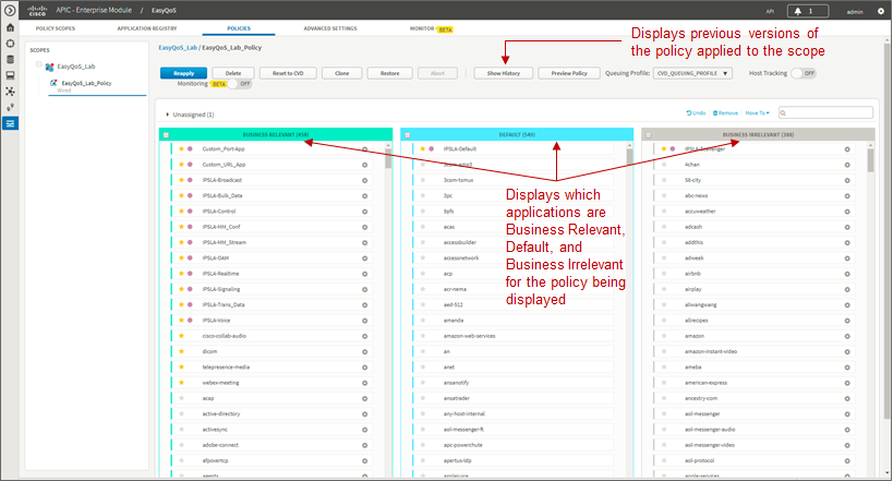
The network operator’s business intent—in terms of the business-relevance of applications—is applied per policy. This means that applications can be assigned different business-relevance attributes in different policies. Here the network operator can view which applications are Business Relevant, Default, and Business Irrelevant for the policy being displayed.
Abort
The network operator can abort the provisioning of the policy to network devices after the policy provisioning has begun, but before the policy provisioning process has completed, by clicking the Abort button. EasyQoS provisions multiple (up to 40) devices at a time. Hence, the abort option is only useful when there are a large number of devices (more than 40) within a policy. Rather than waiting for the entire policy to be provisioned to each device, and then either rolling back the policy or restoring the configuration, the network operator can instead terminate the provisioning of the policy with the Abort button. For policies with a small number of devices, it may be more effective to allow the policy to complete and then either Rollback the policy or Restore the devices to their configuration before EasyQoS policy was applied.
When the Abort button is pressed, EasyQoS cancels the provisioning process only on network devices that have not yet been started to be configured. A light blue bar next to these devices will indicate a status of Policy Aborted for these devices. For devices that have started to be configured, EasyQoS will complete the provisioning of the policy. For devices for which the provisioning of the policy has been completed before the Abort button was pressed, EasyQoS will leave the policy on the device and will update the status of each of these devices—a green bar for Success or a red bar for Failed—based on the outcome of the provisioning of the policy to the device. The network operator can then either Rollback the policy or Restore these devices to their original configuration before EasyQoS policy was applied.
History, Rollback, and Clone
Clicking the Show History button within a policy opens a new Policy History panel in the center of the page, as shown in the following figure.
- Show History
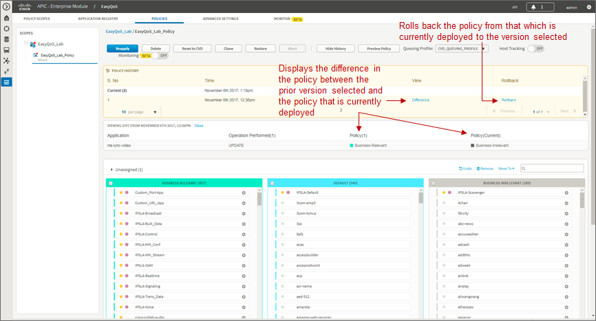
The Policy History panel displays previous versions of the policy selected. The network operator can view the changes in the policy that have been made in the various versions by selecting the Difference feature under a particular prior version. This will display the difference in the policy between the prior version selected and the policy that is currently deployed (it does not display the difference in policy between the prior version selected and the next lower prior version).
The difference in policy is represented in terms of applications—meaning certain applications may have been moved between business relevance, certain applications may have been added or deleted from the Favorites, or custom applications may have been added or deleted. The Difference feature does not display the difference in the actual configuration applied to each network device.
The Rollback feature under a particular prior version can be used to roll back the policy from that which is currently deployed, to the particular prior version selected. This feature is useful in change management scenarios, where a particular change is found to be undesirable and the network infrastructure needs to be rolled-back to the state it was in prior to the change being implemented.
Finally, the Clone button can be used to copy the entire policy. Upon clicking the Clone button, the network operator will be asked to enter a new policy name for the cloned policy and to select a policy scope to which the new cloned policy will be applied. With complex policies, the network operator can save administrative time by not having to duplicate the same policy across multiple policy scopes. After the policy is cloned, the network operator is free to modify it as needed for the particular policy scope.
Restore and Delete
The Restore button deletes an EasyQoS policy and attempts to restore the QoS configuration on all devices covered by the EasyQoS policy back to the original configurations before any EasyQoS policy was applied. Because the EasyQoS policy is deleted when the network operator selects the Restore button, there is no ability to retry the Restore function if it does not succeed in restoring the configuration of all devices to their original (pre-EasyQoS) configuration. This behavior is similar to when the network operator selects the Delete button, in that the EasyQoS policy is deleted. There is no ability to retry the delete function, either.
- Note: If the first attempt to provision an EasyQoS policy to a device (meaning the device initially has no EasyQoS policy) fails, EasyQoS will also automatically attempt to restore the QoS configuration on that device to its original (pre-EasyQoS) configuration.
The network operator should be aware that if a device is removed from an EasyQoS policy after the policy has been applied to the device, the EasyQoS policy will remain on that device. In other words, EasyQoS will not automatically attempt to delete the QoS policy provisioned to the device, nor will EasyQoS attempt to restore the QoS configuration on that device to the original (pre-EasyQoS) configurations.
The Restore button will also not restore the QoS configuration on that device to the original configuration if the original configuration was already an EasyQoS configuration. This situation may occur when upgrading from APIC-EM 1.2 to APIC-EM 1.3 or higher. APIC-EM did not collect the information required to restore the original configuration before provisioning policy in APIC-EM version 1.2.
Finally, there are some parts of the EasyQoS policy that may not be restored, depending upon particular network device platform. The *Pre-Existing QoS Configuration on ISR and ASR Router Platforms* section of the *Branch and WAN Static QoS Design* chapter details what is restored and not restored on router platforms when clicking the Restore button. Likewise, the *Pre-Existing QoS Configuration on Switch Platforms* section of the *Campus LAN Static QoS Design* chapter details what is restored and not restored on switch platforms when clicking the Restore button.
- Note: When an EasyQoS policy is deleted for MLS QoS based switches, the network operator should resynchronize any devices which were part of the policy before applying any new QoS policies. This can be accomplished either by waiting until the polling interval has been exceeded before applying the new policy, or by performing a manual resync of the devices. This will ensure that APIC-EM has the current configuration state of the devices within its database before provisioning EasyQoS policy.
Host Tracking
The Host Tracking feature allows EasyQoS to track Cisco device endpoints discussed within the *Host Inventory* section above, and dynamically apply access-control list entries (ACEs) to the switches to which the devices are connected, as the devices are moved. The ACEs match the voice and video traffic generated by the devices. The Host Tracking feature is enabled per EasyQoS policy through the toggle button shown in the following figure.
- Enabling Host Tracking
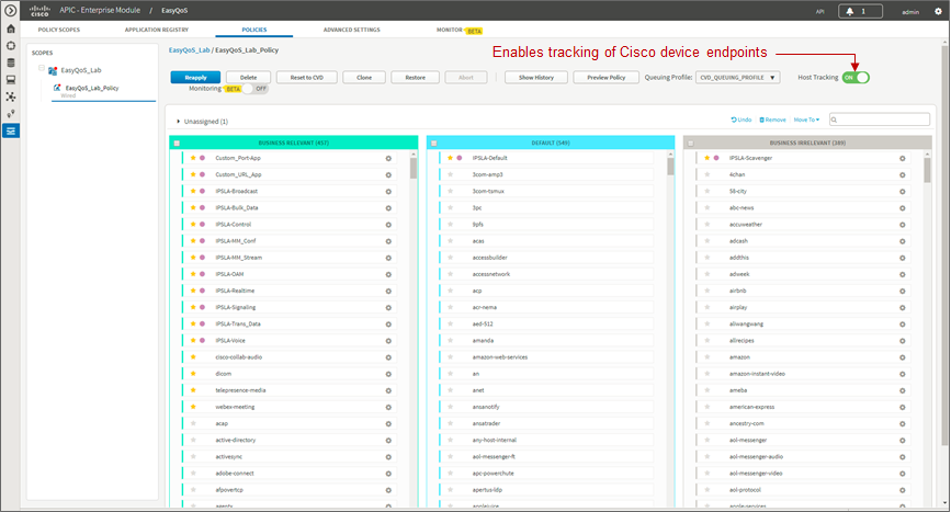
The Host Tracking feature can be enabled as the EasyQoS policy is being created, or after the EasyQoS policy has been created. However, the policy will need to be reapplied to the policy scope if the Host Tracking feature is enabled after the policy has been created. The specific policy configuration created and provisioned to Cisco Catalyst switches, for each device endpoint, is discussed in the *Cisco Device Endpoints* section of the *Campus LAN Static QoS Design* chapter.
Wireless Policies
Cisco AireOS WLCs can also be added to policy scopes by dragging-and-dropping the device into a particular policy scope. Optionally, a separate policy scope can be created for wireless devices. Wireless policies are deployed per WLAN/SSID. If there are multiple WLANs/SSIDs to which EasyQoS policies need to be applied, then the network operator must create a policy for each WLAN/SSID.
A wireless policy (separate from the policy applied for wired devices) must be created under the policy scope. This is done by clicking the blue Create Policy button adjacent to the name of the WLAN/SSID within the Wireless section of the page. As with wired policies, the wireless policy must be given a name; individual applications can be moved between Business-Relevant, Default, and Business-Irrelevant groupings; bi-directionality can be selected for individual applications; and the policy can be previewed before being deployed.
An example of a wireless policy created within an existing policy scope is shown in the figure below.
- Adding a Wireless Policy to a Policy Scope
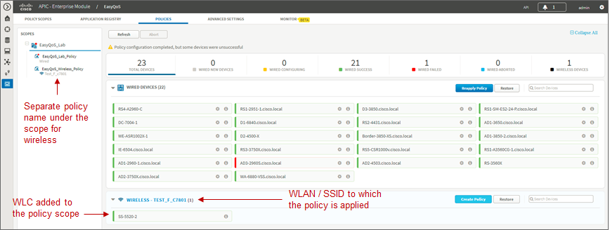
Clicking the wireless policy displays the policy, as shown in the figure below.
- Displaying a Wireless Policy
APIC-EM release 1.6 provides the ability for the network operator to specify whether or not he/she wants to enable the FastLane feature on the WLAN / SSID. The default setting is for the FastLane feature to be disabled. The WLC to which the WLAN / SSID belongs must be running AireOS release 8.3.112 or higher code on order to support the Fastlane feature. Previously with APIC-EM release 1.5, if the WLAN / SSID belonged to a WLC which could support the FastLane feature, the FastLane feature was automatically enabled when EasyQoS policy was provisioned. The FastLane feature is discussed further in *Chapter 10: WLAN QoS Design.*
Applications known via the AVC/NBAR engine within the AireOS WLC are displayed in groupings of Business Relevant, Default, and Business Irrelevant. The network operator can drag-and-drop the applications between the three groupings in order to match the business intent of the organization.
The AVC/NBAR based classification & marking policy deployed to AireOS WLCs specifies an action of mark, rather than drop. For Business Relevant applications, the DSCP marking is by default based on the value of the traffic-class attribute assigned within the NBAR taxonomy. For Business Irrelevant applications, the DSCP marking is by default set to CS1 (DSCP 8). However, DSCP markings for individual applications can be changed within the application registry. DSCP markings for entire traffic-classes can be changed through a custom Queuing Profile applied to the wireless policy. Applications with a business-relevance attribute of Default are not programmed into the AVC/NBAR policy. The AVC/NBAR policy overrides the QoS Profile applied to the WLAN/SSID. Because EasyQoS sets the Maximum Priority field within the QoS Profile to a setting of Voice, for wireless devices which support QoS, applications with a business-relevance attribute of Default are not reset to a DSCP value of Best Effort (DSCP 0). Instead, the WLC allows such applications to pass through with their DSCP values unaltered.
AireOS WLCs support up to 32 applications per QoS Policy. This is a current limitation of the AVC/NBAR engine within AireOS WLCs. By default, EasyQoS will select the 32 applications that get programmed into the wireless policy based upon which applications are selected as Favorites and then based upon the popularity attribute pre-configured for all of the 1300+ applications within the NBAR taxonomy.
Because the network operator has no view of the popularity attribute for any given application within the NBAR taxonomy, there are two methods by which the network operator can guarantee which 32 applications are provisioned into the AireOS AVC/NBAR-based classification & marking policy. Note that the AVC/NBAR-based policy can have less than 32 applications as well, if desired by the network operator.
- In the first method, the network operator can select up to 32 applications as Favorites. APIC-EM will provision applications marked as Favorites before provisioning other applications within the NBAR taxonomy. However, because the choice of Favorites is a global setting—meaning the selection of Favorite applications is the same across all policies in all policy scopes—this may not be an ideal solution.
- In the second method, the network operator can highlight all applications within each of the three groupings—Business Relevant, Default, and Business Irrelevant—via the checkbox at the top of each group. The network operator can then remove all of the applications. This will place all applications for the wireless policy in the Unassigned group. The network operator can then use the search field in the upper right corner of the page to search for each application he/she wants to add back into the policy. Upon locating the application, the network operator must drag-and-drop that application from the Unassigned group into either the Business Relevant or Business Irrelevant grouping. In this manner, the network operator can add up to 32 applications into the wireless policy and ensure they will be provisioned to the AireOS WLC.
As of APIC-EM version 1.3 and higher, the default behavior of the AVC/NBAR-based classification & marking policy is to mark in the upstream direction only. In order to implement bi-directional policies, the network operator must configure bi-directionality for the application. This is done the same way as discussed for Custom applications in the *Policies* section above.
Finally, the network operator should note that Custom applications—regardless of whether they are URL-based or port-based—are not provisioned into the AVC/NBAR-based classification & marking policy of WLC platforms. This is a current limitation of AireOS WLC platforms, in that they do not support the ability to define custom applications within the AVC/NBAR policy.
Upgrading from APIC-EM Release 1.3 to APIC-EM Release 1.4 and Higher
The NBAR protocol pack has been upgraded from version 14.0.0 in APIC-EM release 1.3 to version 27.0.0 in APIC-EM release 1.4 and higher. NBAR protocol pack version 27.0.0 includes additional applications not found in protocol pack 14.0.0. Additionally, some attributes, such as the traffic-class to which an application belongs, may change between protocol pack revisions. This may be the result of better knowledge of how a particular application is used within customer networks over time or the result of changes in how the application itself is used within customer networks over time. Application changes appear as stale applications upon upgrading from APIC-EM release 1.3 to release 1.4 or higher. The network operator should re-apply policies to policy scopes in order to update these stale applications.
Dynamic QoS
For the APIC-EM 1.6 release, Dynamic QoS is still a Beta application within EasyQoS. In order to enable Dynamic QoS, the network operator must access the Advanced Settings tab and then click Dynamic QoS to bring up the screen shown in the figure below.
- Enabling Dynamic QoS

For APIC-EM 1.6 Dynamic QoS is a feature that is enabled globally—meaning across all policy scopes—through the sliding button shown in the figure above. Upon re-applying static QoS policy to a given policy scope, EasyQoS will then provision Dynamic policy-map shells to access-layer switches within that policy scope. The Dynamic policy-map shells are discussed within the *Dynamic QoS Design* chapter of this document.
The Dynamic QoS screen displays the status of Dynamic QoS flows when they are active. Dynamic QoS flows are initiated when call signaling systems, such as CUCM, use the northbound REST-based API to signal to APIC-EM that a call has been established. An example of an active Dynamic QoS session—representing a voice call between two endpoints—is shown in the figure below.
- Example of an Active Dynamic Voice Call
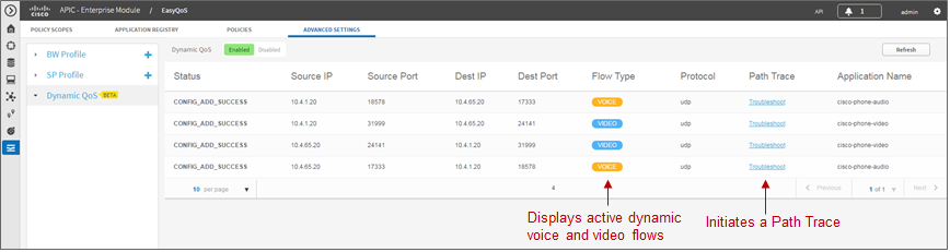
The Path Trace tool can be used to troubleshoot active Dynamic QoS flows by displaying the path of the traffic through the network infrastructure between the endpoints. An example of the Path Trace tool is shown in the figure below.
- Example of the Output of the Path Trace Tool for a Dynamic Flow
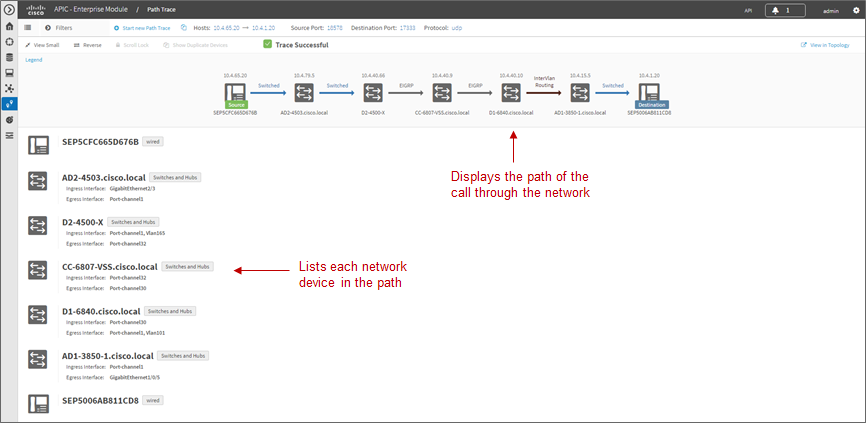
The Path Trace tool displays the path of the traffic associated with the Dynamic QoS flow through the network infrastructure within the top panel of the display. The lower panel provides more detail regarding each of the network devices through which the Dynamic QoS flow passes.
APIC-EM release 1.4 and higher enhanced the REST-based API for Dynamic QoS flows. The API call can now include an Application Name. The Application Name can be used to match one of the existing applications within the NBAR taxonomy or a Custom application. The traffic-class attribute for the Custom application or the application within the NBAR taxonomy must be VoIP Telephony, Multimedia Conferencing, or Real-Time Interactive. EasyQoS will generate an error when an API call attempts to set up a Dynamic QoS flow that includes the Application Name, if the application does not have a traffic-class attribute which matches one of these three traffic-classes.
When call signaling systems, such as CUCM, use the northbound REST-based API to signal to APIC-EM that a call has been terminated, APIC-EM will remove the entry for the Dynamic QoS flow. The *Dynamic QoS Design* chapter of this document has further details regarding the operation of Dynamic QoS.