Chapter 7: Service Provider Managed-Service WAN QoS Design
Challenges
WAN connectivity to a service provider managed-service offering may involve sub-line rate bandwidth provisioning—meaning that the provisioned bandwidth is below the physical interface of the ISR or ASR router platform. For example, it is common to provision a managed-service offering in which the physical connectivity between the Customer Edge router and the Provider Edge router is a Gigabit Ethernet connection. However, the contracted rate between the service provider and the organization is only provisioned for perhaps 50 Mbps or 100 Mbps of total bandwidth.
The contracted rate may be further sub-divided into multiple traffic-classes. It is common for service providers to offer between four and eight traffic-classes. Some of these traffic-classes provide Service Level Agreements for support of real-time (priority) traffic such as voice and video support, while others provide data or best effort service. The number of traffic-classes supported by the service provider, the percentage bandwidth allocation between the traffic-classes, and the supported DSCP markings of those traffic-classes—are collectively referred to as the SPP.
In order to support deployments that have managed-service offerings, APIC-EM must determine the following when deploying QoS policy to ISR/ASR router platforms:
Is a WAN interface connected to a managed-service offering?
If so, what is the sub-line rate of the managed-service offering (if any)?
What is the service provider profile for this managed-service offering—meaning how many traffic-classes are implemented by the service provider, are any eligible for priority treatment, what is the expected mapping of the DSCP values from the traffic-classes within the organization to the traffic-classes within the service-provider, and what are the percentage bandwidth allocations between the service provider traffic-classes?
EasyQoS supports four default SPP models. Each of the default SPP models supports the following:
- A fixed number of traffic-classes (4, 5, 6, and 8 classes)
- A fixed mapping of the DSCP values and priority treatment from the traffic-classes within the organization to the traffic-classes within the service-provider network
- Fixed bandwidth allocations between the service provider traffic-classes
Additionally, as of APIC-EM release 1.3 and higher, EasyQoS supports the ability to create custom SPPs based on the default 4, 5, 6, and 8 class SPP models. Custom service provider profiles allow the network operator to specify the mapping of the DSCP values from the traffic-classes within the organization to the traffic-classes within the service-provider network, as well as to specify the percentage bandwidth allocations between the service provider traffic-classes.
EasyQoS requires the network operator to tag WAN interfaces with a specific string in the interface-description in order to identify the items listed in the three questions above. This must be configured before deploying a QoS policy to the platform via EasyQoS.
There are up to three important fields within the tag. Each of the fields within the tag is delineated via a “#”. The meaning of the fields within the tag is discussed in the following sections.
Identifying WAN Interfaces
EasyQoS requires the network operator to tag WAN interfaces that connect to a service-provider managed service with a specific string in the interface-description: #WAN#. This is the first field in the overall tag discussed in the previous section, and is a required field.
An example of the configuration is shown below with the first part of the tag highlighted.
!
interface GigabitEthernet0/0
description CIRCUIT TO WE-ASR2 GIG-0-0-1 #WAN#50M#SPP:New-6-Class#
!
- Note: If the network operator has configured no tag on a WAN interface, EasyQoS applies the WAN-Edge Egress Queuing Policy discussed in the *WAN and Branch Static QoS Design* chapter. This is because the WAN-Edge Egress Queuing Policy is also applied to LAN connections between the ISR or ASR platform and the Catalyst switch, and LAN connections are not required to have any tag within their interface descriptions.
Currently the #WAN# part of the overall tag provides no additional functionality in the context of a service-provider managed-service other than to identify the interface as a WAN connection.
Identifying Sub-Line Rate WAN Interfaces
Optionally, when connecting to a service provider managed-service using sub-line rate connectivity EasyQoS requires the network operator to tag WAN interfaces with the sub-line rate—meaning the overall provisioned bandwidth of the service contracted from the service provider. The sub-line rate is tagged with a specific string in the interface-description: #rate#. This is the second field in the overall tag discussed previously. If a sub-line rate service is not provisioned, this field can be omitted within the overall tag.
An example of the configuration is shown below with the second part of the tag highlighted.
!
interface GigabitEthernet0/0
description CIRCUIT TO WE-ASR2 GIG-0-0-1 #WAN#50M#SPP:New-6-Class#
!
The rate is specified using abbreviations—“M” for Mbps. In the example above “50M” stands for a sub-line rate of 50 Mbps contracted from the service provider. This rate is read by APIC-EM during inventory process and is then used by EasyQoS to provision the shaper at the top-level of the hierarchical egress queuing policy. This shaper is necessary to provide the back-pressure in order for QoS to be engaged on the WAN link, when implementing a sub-line rate service.
Identifying WAN Interfaces Mapped to SP Class-of-Service Models
EasyQoS requires the network operator to tag WAN interfaces with either the name of one of the four default SPPs or the name of a custom profile, when connected to a service provider managed-service. The format of the tag is dependent upon whether one of the four default service provider profiles is to be attached to the interface or whether a custom service provider profile is to be attached to the interface.
Default Service Provider Profiles
When implementing one of the four default service provider profiles, the format of the tag can take one of the two forms.
The first form provides backward compatibility with prior versions of APIC-EM EasyQoS.
#WAN#rate#SPPx#
The “x” in “SPPx” refers to one of the four default service provider profiles, which are discussed in detail in the following sections.
The second form is uses the same format as custom service provider profiles.
#WAN#rate#SPP:SPPx-yClass
The “x” in SPP:SPPx-yClass” refers to one of the four default service provider profiles, which are discussed in detail in the following sections. The “y” in “SPP:SPPx-yClass” refers to the number of traffic-classes supported by the service provider.
The two forms can be used to express the same service provider profile as shown below:
- SPP1 = SPP:SPP1-4Class
- SPP2 = SPP:SPP2-5Class
- SPP3 = SPP:SPP3-6Class
- SPP-4 = SPP:SPP4-8Class
An example of the configuration of an interface description using the default service provider profile SPP1 within the tag is shown below, with the third part of the tag highlighted.
!
interface GigabitEthernet0/0
description CIRCUIT TO WE-ASR2 GIG-0-0-1 #WAN#50M#SPP1#
!
Custom Service Provider Profiles
When implementing one of the custom service provider profiles, the format of the tag is as follows:
#WAN#rate#SPP:custom_profile_name#
The “custom_profile_name” refers to the name of the custom service provider profile created within the EasyQoS GUI. This is discussed in the *APIC-EM and the EasyQoS Application* chapter of this document. An example of the configuration of an interface description using a custom service provider profile named “New-6-Class” within the tag is shown below, with the third part of the tag highlighted.
!
interface GigabitEthernet0/0
description CIRCUIT TO WE-ASR2 GIG-0-0-1 #WAN#50M#SPP1:New-6-Class#
!
Each of the four default service provider profiles, as well as custom service provider profiles is discussed in the *Service Provider Default Class of Service Models* section below.
- Note: If the tag within the interface description is added, removed, or modified, the network operator must wait until APIC-EM re-synchronizes the configuration of the ISR or ASR router by running its inventory process again before re-applying any QoS policy to the device. APIC-EM will synchronize the configuration of network devices approximately every 25 minutes by default, although the polling interval can be modified as of APIC-EM release 1.4 and higher. Alternatively, the network operator can manually sync the device, which is another new feature added to APIC-EM release 1.4 and higher. If a QoS policy is re-applied to the device by EasyQoS before APIC-EM has re-synchronized the configuration with its internal database, the EasyQoS policy may not reflect the desired changes to the policy, based on the changes to the interface description.
Service Provider Default Class of Service Models
EasyQoS supports connectivity to service provider managed-service offerings, using one of the following four default SPP class-of-service models for ISR and ASR router platforms:
- SPP1/SPP:SPP1-4Class
- SPP2/SPP:SPP2-5Class
- SPP3/SPP:SPP3-6Class
- SPP4/SPP:SPP4-8Class
Because queuing is done in software on ISR and ASR router platforms, all SPP models implement an egress queuing policy consisting of 12 egress queues—one for each of the traffic-classes as shown in Figure 5 earlier in this document.
APIC-EM determines which of the four SPP models to deploy based on the #SPPx#” field (where x is from 1 to 4) or “#SPP:SPPx-yClass#” (where x is from 1 to 4 and y is 4, 5, 6, or 8) within the description configured on the ISR or ASR WAN interface connected to the service provider managed-service.
SPP1 or SPP:SPP1-4Class
The SPP1/SPP:SPP1-4Class service provider profile is based on managed-service offerings with four traffic-classes. These traffic-classes are specified as follows within this document:
- SP-Voice
- SP-Class1Data
- SP-Class2Data
- SP-Default
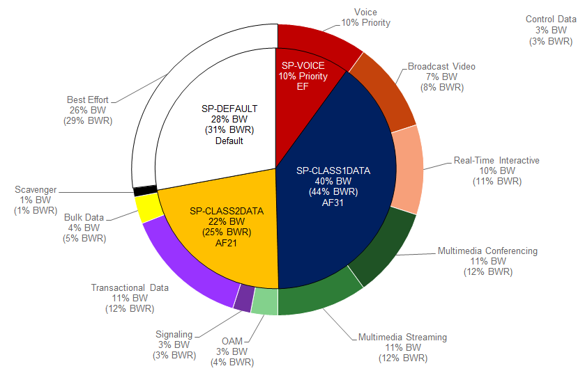
The following figure shows the WAN bandwidth allocation for the SPP1/SPP:SPP1-4Class service provider profile.
- WAN Bandwidth Allocation for the SPP1/SPP:SPP1-4Class
The egress queuing policy class-map definitions provisioned by EasyQoS for all of the SPPs discussed here are the same as was as discussed in the *WAN-Edge Egress Queuing Policy* section of the *WAN and Branch Static QoS Design* chapter, and will not be duplicated here.
For the SPP1/SPP:SPP1-4Class model, EasyQoS must map the RFC 4594-based 12-class QoS model implemented within the organization into the four traffic-classes provide by the service provider. The following figure shows this mapping with the bandwidth allocations and traffic re-marking for the service provider traffic-classes.
- EasyQoS Marking Mappings Into SPP1/SPP:SPP1-4Class

The following is an example of the hierarchical policy-map definition provisioned by EasyQoS that implements the SPP1/SPP:SPP1-4Class egress queuing policy with the bandwidths and traffic re-marking for each of the service provider traffic-classes. It assumes a sub-line rate of 50 Mbps to the service provider network.
!
policy-map prm-dscp#EQ_SPP1-4Class#shape#50.0
class class-default
shape average 50000000
service-policy prm-dscp#EQ_SPP1-4Class
!
policy-map prm-dscp#EQ_SPP1-4Class
class prm-EZQOS_12C#VOICE
police rate percent 10
priority
set dscp ef
class prm-EZQOS_12C#BROADCAST
bandwidth remaining percent 8
set dscp af31
class prm-EZQOS_12C#REALTIME
bandwidth remaining percent 11
set dscp af31
class prm-EZQOS_12C#MM_CONF
bandwidth remaining percent 12
fair-queue
set dscp af31
random-detect dscp-based
class prm-EZQOS_12C#MM_STREAM
bandwidth remaining percent 12
fair-queue
set dscp af31
random-detect dscp-based
class prm-EZQOS_12C#CONTROL
bandwidth remaining percent 3
class prm-EZQOS_12C#SIGNALING
bandwidth remaining percent 3
set dscp af21
class prm-EZQOS_12C#OAM
bandwidth remaining percent 4
set dscp af21
class prm-EZQOS_12C#TRANS_DATA
bandwidth remaining percent 12
fair-queue
set dscp af21
random-detect dscp-based
class prm-EZQOS_12C#BULK_DATA
bandwidth remaining percent 5
fair-queue
set dscp af21
random-detect dscp-based
class prm-EZQOS_12C#SCAVENGER
bandwidth remaining percent 1
set dscp default
class class-default
bandwidth remaining percent 29
fair-queue
set dscp default
random-detect dscp-based
random-detect dscp 0 50 64 ! ISR G2 Series platforms only.
!
The names of the parent and child policy-maps reflect the SPP configured for the WAN interface. When using the newer method where the service provider profile is indicated via the #SPP:SPP1-4Class# tag, the format of the parent and child policy-maps will be as follows:
!
policy-map prm-dscp#EQ_SPP1-4Class#shape#50.0
policy-map prm-dscp#EQ_SPP1-4Class
!
This is the format shown in the configuration example above.
When using the older method where the service provider profile is indicated via the #SPP1#” tag, the format of the parent and child policy-maps will be as follows:
!
policy-map prm-dscp#EQ_1#shape#50.0
policy-map prm-dscp#EQ_1
!
If a sub-line rate service has been provisioned, the top-level of the SPP1/SPP:SPP1-4Class hierarchical egress queuing policy-map simply implements shaping to an average rate that matches the sub-line bandwidth rate of the managed-service offering provisioned by the service provider. This rate is learned via the #rate# field within the tag, which must be pre-configured within the description of the interface connected to the managed service WAN link.
- Note: If a sub-line rate service has not been provisioned, EasyQoS will not configure a hierarchical policy-map with a shaper at the parent-level. Instead, the policy-map will only have a single level with the configuration similar to the child-policy discussed below.
The child-policy of the SPP1/SPP:SPP1-4Class egress queuing policy-map implements a single LLQ policy, meaning a separate LLQ for the Voice traffic class. An explicit policer (10% of bandwidth) for the Voice queue ensures that the LLQ can use no more than the percentage of the bandwidth of the WAN link allocated to the Voice traffic class, regardless of whether there is available bandwidth.
The remaining eleven queues share the remaining bandwidth based on a percentage allocation of bandwidth. This is accomplished via the “bandwidth remaining percent” command. Each of these queues can use more than its percentage allocation, if more bandwidth is available—meaning if one or more of the other queues is not using its full allocation of remaining bandwidth percentage.
The following traffic is admitted (mapped) to the service provider SP-Voice traffic class. Traffic mapped to this service provider traffic class is remarked to EF.
- Traffic exiting the Voice queue
The bandwidth allocated to the Voice queue (10% priority and policed) is meant to match the 10% bandwidth allocation of the service provider SP-Voice traffic class as shown in Figure 66.
The following traffic is admitted (mapped) to the service provider SP-Class1Data traffic class. Traffic mapped to this service provider traffic class is remarked to AF31.
- Traffic exiting the Broadcast-Video queue re-marked from CS5
- Traffic exiting the Realtime-Interactive queue re-marked from CS4
- Traffic exiting the Multimedia-Conferencing queue re-marked from AF4x
- Traffic exiting the Multimedia-Streaming queue re-marked from AF3x
The sum of the bandwidths allocated to four queues—Broadcast-Video (8% bandwidth remaining), Realtime-Interactive (11% bandwidth remaining), Multimedia-Conferencing (12% bandwidth remaining), and Multimedia-Streaming (12% bandwidth remaining)—is meant to roughly match the 44% bandwidth remaining allocation of the service provider SP-Class1Data traffic class as shown in Figure 66.
The following traffic is admitted (mapped) to the service provider SP-Class2Data traffic class. Traffic mapped to this service provider traffic class is remarked to AF21.
- Traffic exiting the Signaling queue re-marked from AF3x
- Traffic exiting the OAM queue remarked from CS2
- Traffic exiting the Transactional-Data queue marked from AF2x
- Traffic exiting the Bulk-Data queue re-marked from AF1x
The sum of the bandwidths allocated to the four queues—Signaling (3% bandwidth), OAM (4% bandwidth), Transactional-Data (12% bandwidth remaining), and Bulk-Data (5% bandwidth remaining)—is meant to roughly match the 25% bandwidth remaining allocation of the service provider SP-Class2Data traffic class, as shown in Figure 66.
The following traffic is admitted (mapped) to the service provider SP-Default traffic class. Traffic mapped to this service provider traffic class is remarked to Default (Best Effort).
- Traffic exiting the Scavenger queue is re-marked from CS1
- Traffic exiting the Default queue
The sum of the bandwidth allocated to two queues—Scavenger (1% bandwidth remaining) and Default (29% bandwidth remaining)—is meant to roughly match the default 31% bandwidth remaining allocation of the service provider SP-Default traffic class, as shown in Figure 66.
Fair-queuing, along with DSCP-based WRED is implemented for the following queues:
- Multimedia-Conferencing
- Multimedia-Streaming
- Transactional-Data
- Bulk-Data
- Default
For ISR 3900, 2900, and 800 Series (ISR G2) platforms only, with the exception of the Default queue, minimum and maximum WRED thresholds for the queues are left at their default values. Table 5 summarized these minimum and maximum thresholds. The default WRED thresholds for the Default queue are considered to be too aggressive—meaning the minimum drop threshold is set lower than desired. Hence, the minimum drop threshold has been adjusted to 50 packets, and the maximum drop threshold adjusted to the depth of the queue—64 packets. For ISR 4400 and ASR 1000 Series platforms the minimum and maximum WRED thresholds for the queues are left at their default values.
Traffic within the Control queue is sent unchanged to the service provider network and is not considered to be mapped into one of the four service provider traffic-classes.
The SPP1/SPP:SPP1-4Class egress queuing policy is applied to WAN interfaces that include the #WAN#rate#SPP1# or #WAN#rate#SPP:SPP1-4Class# tag within the interface description.
An example of the application of the egress queuing policy is as follows:
!
interface GigabitEthernet0/0/3
description TO PE2-3600X #WAN#50M#SPP:SPP1-4Class#
service-policy output prm-dscp#EQ_SPP1-4Class#shape#50.0
!
SPP2/SPP:SPP2-5Class
The SPP2/SPP:SPP2-5Class service provider profile is based on managed-service offerings with five traffic-classes. These traffic-classes are specified as follows within this document:
- SP-Voice
- SP-Class1Data
- SP-Class2Data
- SP-Class3Data
- SP-Default
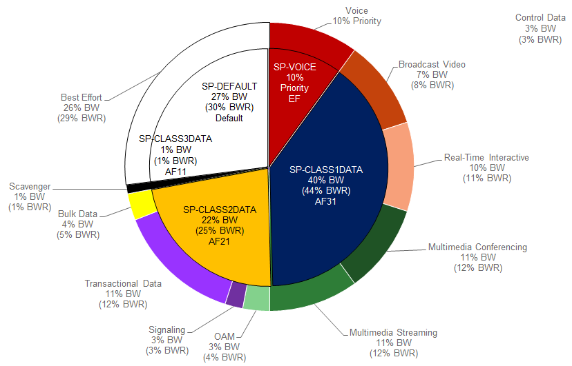
The following figure shows the WAN bandwidth allocation model for the SPP2/SPP:SPP2-5Class service provider profile.
- WAN Bandwidth Allocation for the SPP2/SPP:SPP2-5Class
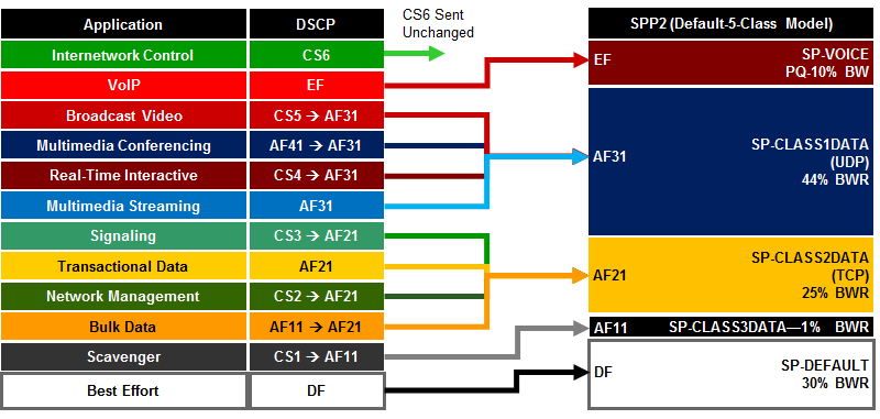
For the SPP2/SPP:SPP2-5Class, EasyQoS must map the RFC 4594-based 12-class QoS model implemented within the organization into the five traffic-classes provide by the service provider. The following figure shows this mapping with the bandwidth allocations and traffic re-marking for the service provider traffic-classes.
- EasyQoS Marking Mappings into SPP2/SPP:SPP2-5Class
The following is an example of the hierarchical policy-map definition provisioned by EasyQoS that implements the SPP2/SPP:SPP2-5Class queuing policy with the bandwidths and traffic re-marking for each of the service provider traffic-classes. It assumes a sub-line rate of 50 Mbps to the service provider network.
!
policy-map prm-dscp#EQ_SPP2-5Class#shape#50.0
class class-default
shape average 50000000
service-policy prm-dscp#EQ_SPP2-5Class
!
policy-map prm-dscp#EQ_SPP2-5Class
class prm-EZQOS_12C#VOICE
police rate percent 10
priority
set dscp ef
class prm-EZQOS_12C#BROADCAST
bandwidth remaining percent 8
set dscp af31
class prm-EZQOS_12C#REALTIME
bandwidth remaining percent 11
set dscp af31
class prm-EZQOS_12C#MM_CONF
bandwidth remaining percent 12
fair-queue
set dscp af31
random-detect dscp-based
class prm-EZQOS_12C#MM_STREAM
bandwidth remaining percent 12
fair-queue
set dscp af31
random-detect dscp-based
class prm-EZQOS_12C#CONTROL
bandwidth remaining percent 3
class prm-EZQOS_12C#SIGNALING
bandwidth remaining percent 3
set dscp af21
class prm-EZQOS_12C#OAM
bandwidth remaining percent 4
set dscp af21
class prm-EZQOS_12C#TRANS_DATA
bandwidth remaining percent 12
fair-queue
set dscp af21
random-detect dscp-based
class prm-EZQOS_12C#BULK_DATA
bandwidth remaining percent 5
fair-queue
set dscp af21
random-detect dscp-based
class prm-EZQOS_12C#SCAVENGER
bandwidth remaining percent 1
set dscp af11
class class-default
bandwidth remaining percent 29
fair-queue
set dscp default
random-detect dscp-based
random-detect dscp 0 50 64 ! ISR G2 Series platforms only.
!
Again, the names of the parent and child policy-maps reflect the SPP configured for the WAN interface. When using the newer method where the service provider profile is indicated via the #SPP:SPP2-5Class# tag, the format of the parent and child policy-maps will be as follows:
!
policy-map prm-dscp#EQ_SPP2-5Class#shape#50.0
policy-map prm-dscp#EQ_SPP2-5Class
!
This is the format shown in the configuration example above.
When using the older method where the service provider profile is indicated via the #SPP2#” tag, the format of the parent and child policy-maps will be as follows:
!
policy-map prm-dscp#EQ_2#shape#50.0
policy-map prm-dscp#EQ_2
!
The difference between the SPP1 and SPP2 models is that a 5th service provider traffic class—SP-Class3Data—is provisioned specifically for handling traffic with a lower than best-effort treatment (Scavenger traffic).
The policy-map admits and re-marks traffic exiting the Scavenger queue from CS1 to AF11, corresponding to the service provider SP-Class3Data traffic class. The bandwidth allocated to the Scavenger queue (1% bandwidth remaining) is meant to match the 1% bandwidth remaining allocated to the service provider SP-Class3Data traffic class, as shown in Figure 68.
The SPP2/SPP:SPP2-5Class egress queuing policy is applied to WAN interfaces that include the #WAN#rate#SPP2# or #WAN#rate#SPP:SPP2-5Class# tag within the interface description.
An example of the application of the egress queuing policy is as follows:
!
interface GigabitEthernet0/0/5
description APIC-EM-1.4-TEST #WAN#50M#SPP:SPP2-5Class#
service-policy output prm-dscp#EQ_SPP2-5Class#shape#50.0
!
SPP3/SPP:SPP3-6Class
The SPP3/SPP:SPP3-6Class service provider profile is based on managed-service offerings with six traffic-classes. These traffic-classes are specified as follows within this document:
- SP-Voice
- SP-Video
- SP-Class1Data
- SP-Class2Data
- SP-Class3Data
- SP-Default
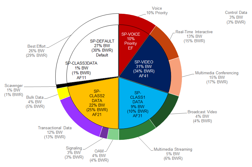
The following figure shows the WAN bandwidth allocation model for the SPP3/SPP:SPP3-6Class service provider profile.
- WAN Bandwidth Allocation for the SPP3/SPP:SPP3-6Class
For the SPP3/SPP:SPP3-6Class, EasyQoS must map the RFC 4594-based 12-class QoS model implemented within the organization into the six traffic-classes provide by the service provider. The following figure shows this mapping with the bandwidth allocations and traffic re-marking for the service provider traffic-classes.
- EasyQoS marking Mappings Into SPP3/SPP:SPP3-6Class
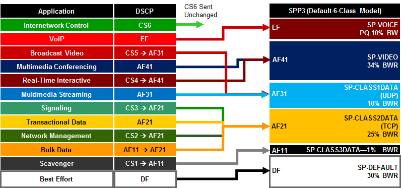
The following is an example of the hierarchical policy-map definition provisioned by EasyQoS that implements the SPP3/SPP:SPP3-6Class queuing policy, with the bandwidths and traffic re-marking for each of the service provider traffic-classes. It assumes a sub-line rate of 50 Mbps to the service provider network.
!
policy-map prm-dscp#EQ_SPP3-6Class#shape#50.0
class class-default
shape average 50000000
service-policy prm-dscp#EQ_SPP3-6Class
!
policy-map prm-dscp#EQ_SPP3-6Class
class prm-EZQOS_12C#VOICE
police rate percent 10
priority
set dscp ef
class prm-EZQOS_12C#BROADCAST
bandwidth remaining percent 4
set dscp af31
class prm-EZQOS_12C#REALTIME
bandwidth remaining percent 15
set dscp af41
class prm-EZQOS_12C#MM_CONF
bandwidth remaining percent 17
fair-queue
set dscp af41
random-detect dscp-based
class prm-EZQOS_12C#MM_STREAM
bandwidth remaining percent 6
fair-queue
set dscp af31
random-detect dscp-based
class prm-EZQOS_12C#CONTROL
bandwidth remaining percent 3
class prm-EZQOS_12C#SIGNALING
bandwidth remaining percent 3
set dscp af21
class prm-EZQOS_12C#OAM
bandwidth remaining percent 4
set dscp af21
class prm-EZQOS_12C#TRANS_DATA
bandwidth remaining percent 13
fair-queue
set dscp af21
random-detect dscp-based
class prm-EZQOS_12C#BULK_DATA
bandwidth remaining percent 5
fair-queue
set dscp af21
random-detect dscp-based
class prm-EZQOS_12C#SCAVENGER
bandwidth remaining percent 1
set dscp af11
class class-default
bandwidth remaining percent 29
fair-queue
set dscp default
random-detect dscp-based
random-detect dscp 0 50 64 ! ISR G2 Series platforms only.
!
The names of the parent and child policy-maps reflect the SPP configured for the WAN interface. When using the newer method where the service provider profile is indicated via the #SPP:SPP3-6Class# tag, the format of the parent and child policy-maps will be as follows:
!
policy-map prm-dscp#EQ_SPP3-6Class#shape#50.0
policy-map prm-dscp#EQ_SPP3-6Class
!
This is the format shown in the configuration example above.
When using the older method where the service provider profile is indicated via the #SPP3#” tag, the format of the parent and child policy-maps will be as follows:
!
policy-map prm-dscp#EQ_3#shape#50.0
policy-map prm-dscp#EQ_3
!
The difference between the SPP2 and SPP3 models is that a 6th service provider traffic class—SP-Video—is provisioned specifically for handling video traffic.
The following traffic is admitted (mapped) to the service provider SP-Video traffic class. Traffic mapped to this service provider traffic class is remarked to AF41.
- Traffic exiting the Realtime-Interactive queue is re-marked from CS4
- Traffic exiting the Multimedia-Conferencing re-marked from AF4x
The sum of the bandwidth allocated to two queues—Realtime-Interactive (15% bandwidth remaining) and Multimedia-Conferencing (17% bandwidth remaining)—is meant to roughly match the 34% bandwidth remaining allocation of the service provider SP-Class1Data traffic class as shown in Figure 70.
The mappings are also adjusted so that the following is admitted (mapped) to the service provider SP-Class1Data traffic class. Traffic mapped to this service provider traffic class is remarked to AF31.
- Traffic exiting the Broadcast-Video queue is re-marked from CS5
- Traffic exiting the Multimedia-Streaming queue is re-marked from AF3x
The sum of the bandwidth allocated to two queues—Broadcast-Video (4% bandwidth remaining) and Multimedia-Streaming (6% bandwidth remaining)—is meant to roughly match the 10% bandwidth remaining allocation of the service provider SP-Streaming-Video traffic class as shown in Figure 70.
The SPP3/SPP:SPP3-6Class egress queuing policy is applied to WAN interfaces that include the #WAN#rate#SPP3# or #WAN#rate#SPP:SPP3-6Class# tag within the interface description.
An example of the application of the egress queuing policy is as follows:
!
interface GigabitEthernet0/0/3.10
description #WAN#50M#SPP:SPP3-6Class#
service-policy output prm-dscp#EQ_SPP3-6Class#shape#50.0
!
SPP4/SPP:SPP4-8Class
The SPP4/SPP:SPP4-8Class service provider profile is based on managed-service offerings with eight traffic-classes. These traffic-classes are specified as follows within this document:
- SP-Voice
- SP-Interactive-Video
- SP-Streaming-Video
- SP-Net-Ctrl-Mgmt
- SP-Call-Sig
- SP-Critical-Data
- SP-Scavenger
- SP-Default
The following figure shows the WAN bandwidth allocation model for the SPP4/SPP:SPP4-8Class service provider profile.
- WAN Bandwidth Allocation for the SPP4/SPP:SPP4-8Class
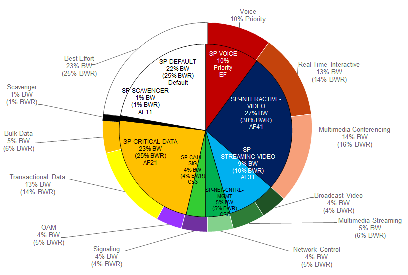
For the SPP4/SPP:SPP4-8Class, EasyQoS must map the RFC 4594-based 12-class QoS model implemented within the organization into the eight traffic-classes provide by the service provider. The following figure shows this mapping with the bandwidth allocations and traffic re-marking for the service provider traffic-classes.
- EasyQoS Marking Mappings into SPP4

The following is an example of the hierarchical policy-map definition provisioned by EasyQoS that implements the SPP4/SPP:SPP4-8Class queuing policy with the bandwidths and traffic re-marking for each of the service provider traffic-classes. It assumes a sub-line rate of 50 Mbps to the service provider network.
!
policy-map prm-dscp#EQ_SPP4-8Class#shape#50.0
class class-default
shape average 50000000
service-policy prm-dscp#EQ_SPP4-8Class
!
policy-map prm-dscp#EQ_SPP4-8Class
class prm-EZQOS_12C#VOICE
police rate percent 10
priority
set dscp ef
class prm-EZQOS_12C#BROADCAST
bandwidth remaining percent 4
set dscp af31
class prm-EZQOS_12C#REALTIME
bandwidth remaining percent 14
set dscp af41
class prm-EZQOS_12C#MM_CONF
bandwidth remaining percent 16
fair-queue
set dscp af41
random-detect dscp-based
class prm-EZQOS_12C#MM_STREAM
bandwidth remaining percent 6
fair-queue
set dscp af31
random-detect dscp-based
class prm-EZQOS_12C#CONTROL
bandwidth remaining percent 5
set dscp cs6
class prm-EZQOS_12C#SIGNALING
bandwidth remaining percent 4
set dscp cs3
class prm-EZQOS_12C#OAM
bandwidth remaining percent 5
set dscp af21
class prm-EZQOS_12C#TRANS_DATA
bandwidth remaining percent 14
fair-queue
set dscp af21
random-detect dscp-based
class prm-EZQOS_12C#BULK_DATA
bandwidth remaining percent 6
fair-queue
set DSCP af21
random-detect dscp-based
class prm-EZQOS_12C#SCAVENGER
bandwidth remaining percent 1
set dscp cs1
class class-default
bandwidth remaining percent 25
fair-queue
set dscp default
random-detect dscp-based
random-detect dscp 0 50 64 ! ISR G2 Series platforms only.
!
As with the previous service provider profile models, the names of the parent and child policy-maps reflect the SPP configured for the WAN interface. When using the newer method where the service provider profile is indicated via the #SPP:SPP4-8Class# tag, the format of the parent and child policy-maps will be as follows:
!
policy-map prm-dscp#EQ_SPP4-8Class#shape#50.0
policy-map prm-dscp#EQ_SPP4-8Class
!
This is the format shown in the configuration example above.
When using the older method where the service provider profile is indicated via the #SPP4#” tag, the format of the parent and child policy-maps will be as follows:
!
policy-map prm-dscp#EQ_4#shape#50.0
policy-map prm-dscp#EQ_4
!
If a sub-line rate service has been provisioned, the top-level of the SPP4/SPP:SPP4-8Class hierarchical egress queuing policy-map simply implements shaping to an average rate that matches the sub-line bandwidth rate of the managed-service offering provisioned by the service provider. This rate is learned via the #rate# field within the tag, which must be pre-configured within the description of the interface connected to the managed service WAN link.
The child-policy of the SPP4/SPP:SPP4-8Class egress queuing policy-map implements a single LLQ policy, meaning a separate LLQ for the Voice traffic class. An explicit policer (10% of the bandwidth) for the Voice queue ensures that the LLQ can use no more than the percentage of the bandwidth of the WAN link allocated to the traffic class, regardless of whether there is available bandwidth.
The remaining eleven queues share the remaining bandwidth based on a percentage allocation of bandwidth. This is accomplished via the “bandwidth remaining percent” command. Each of these queues can use more than its percentage allocation, if more bandwidth is available—meaning if one or more of the other queues is not using its full allocation of remaining bandwidth percentage.
The following traffic is admitted (mapped) to the service provider SP-Voice traffic class. Traffic mapped to this service provider traffic class is remarked to EF.
- Traffic exiting the Voice queue
The bandwidth allocated to the Voice queue (10% priority and policed) is meant to match the 10% bandwidth remaining allocation of the service provider SP-Voice traffic class as shown in Figure 72.
The following traffic is admitted (mapped) to the service provider SP-Net-Ctrl-Mgmt traffic class. Traffic mapped to this service provider traffic class is remarked to CS6.
- Traffic exiting the Control queue
The bandwidth allocated to the Control queue (5% bandwidth remaining) is meant to roughly match the 5% bandwidth remaining allocation of the service provider SP-Net-Ctrl-Mgmt traffic class as shown in Figure 72.
The following traffic is admitted (mapped) to the service provider SP-Interactive-Video traffic class. Traffic mapped to this service provider traffic class is remarked to AF41
- Traffic exiting the Realtime-Interactive queue re-marked from CS4
- Traffic exiting the Multimedia-Conferencing queue re-marked from AF4x
The sum of the bandwidth allocated to two queues—Realtime-Interactive (14% bandwidth remaining) and Multimedia-Conferencing (16% bandwidth remaining)—is meant to roughly match the 30% bandwidth remaining allocation of the service provider SP-Class1Data traffic class as shown in Figure 72.
The following traffic is admitted (mapped) to the service provider SP-Streaming-Video traffic class. Traffic mapped to this service provider traffic class is remarked to AF31
- Traffic exiting the Broadcast-Video queue re-marked from CS5
- Traffic exiting the Multimedia-Streaming queue re-marked from AF3x
The sum of the bandwidth allocated to two queues—Broadcast-Video (4% bandwidth remaining) and Multimedia-Streaming (6% bandwidth remaining)—is meant to roughly match the default 10% bandwidth remaining allocation of the service provider SP-Streaming-Video traffic class as shown in Figure 72.
The following traffic is admitted (mapped) to the service provider SP-Call-Signaling traffic class. By default traffic mapped to this service provider traffic class is remarked to CS3
- Traffic exiting the Signaling queue
The bandwidth allocated to the Signaling queue (4% bandwidth remaining) is meant to roughly match the 4% bandwidth remaining allocation of the service provider SP-Call-Signaling traffic class as shown in Figure 72.
The following traffic is admitted (mapped) to the service provider SP-Critical-Data traffic class. Traffic mapped to this service provider traffic class is remarked to AF21
- Traffic exiting the OAM queue re-marked from CS2
- Traffic exiting the Transactional-Data queue re-marked from AF2x
- Traffic exiting the Bulk-Data queue re-marked from AF1x
The sum of the bandwidth allocated to the three queues—OAM (5% bandwidth remaining), Transactional-Data (14% bandwidth remaining), and Bulk-Data (6% bandwidth remaining)—is meant to roughly match the 25% bandwidth remaining allocation of the service provider SP-Critical-Data traffic class, as shown in Figure 72.
The following traffic is admitted (mapped) to the service provider SP-Scavenger traffic class. Traffic mapped to this service provider traffic class is remarked to CS1.
- Traffic exiting the Scavenger queue
The bandwidth allocated to the Scavenger queue (1% bandwidth remaining) is meant to roughly match the 1% bandwidth remaining allocation of the service provider SP-Scavenger traffic class as shown in Figure 72.
The following traffic is admitted (mapped) to the service provider Default traffic class:
- Traffic exiting the Default queue
The bandwidth allocated to the Default queue (25% bandwidth remaining) is meant to roughly match the 25% bandwidth remaining allocation of the service provider SP-Default traffic class as shown in Figure 72.
Fair-queuing, along with DSCP-based WRED is implemented for the following queues:
- Multimedia-Conferencing
- Multimedia-Streaming
- Transactional-Data
- Bulk-Data
- Default
For ISR 3900, 2900, and 800 Series (ISR G2) platforms only, with the exception of the Default queue, minimum and maximum WRED thresholds for the queues are left at their default values. Table 5 summarized these minimum and maximum thresholds. The default WRED thresholds for the Default queue are considered to be too aggressive—meaning the minimum drop threshold is set lower than desired. Hence, the minimum drop threshold has been adjusted to 50 packets, and the maximum drop threshold adjusted to the depth of the queue—64 packets. For ISR 4400 Series platforms the minimum and maximum WRED thresholds for the queues are left at their default values.
The SPP4/SPP:SPP4-8Class egress queuing policy is applied to WAN interfaces that include the #WAN#rate#SPP4# or #WAN#rate#SPP:SPP4-8Class# tag within the interface description.
An example of the application of the egress queuing policy is as follows:
!
interface GigabitEthernet0/0/4.100
description APIC-EM-1.4-TEST #WAN#50M#SPP:SPP4-8Class#
service-policy output prm-dscp#EQ_SPP4-8Class#shape#50.0
!
Custom Service Provider Profiles
Configuration of custom service provider profiles is discussed in the *APIC-EM and the EasyQoS Application* chapter. Custom service provider profiles use one of the four default service provider profiles discussed in the sections above as a template for the custom profile. Hence the basic structure of the egress queuing policy is the same as discussed in the sections above.
The mapping of the internal queues to the service provider traffic-classes is fixed, depending upon which of the four default service provider profiles has been selected as the template upon which to base the custom service provider profile. In other words, the internal traffic-classes that are admitted to each service provider traffic class is fixed based upon the 4, 5, 6, or 8-class template chosen for the custom service provider profile. However, the DSCP value to which the internal traffic-classes are re-marked as they enter the service provider network can be specified by the network operator when configuring the custom service provider profile.
The percentage of bandwidth allocated to the service provider traffic-classes can also be specified by the network operator when configuring the custom service provider profile. If a sub-line rate service has been provisioned and the interface includes a #rate# tag within the description, then a hierarchical policy-map will be configured by EasyQoS, with a shaper matching the sub-line rate configured at the parent level.
The child-policy of the egress queuing policy-map will still implement a single LLQ policy, meaning a separate LLQ for only the Voice traffic class. An explicit policer for the Voice queue ensures that the LLQ can use no more than the percentage of the bandwidth of the WAN link allocated to the Voice traffic class, regardless of whether there is available bandwidth. For a custom service provider profile, the percentage of bandwidth allocated to the policer is directly dependent upon the amount of bandwidth allocated to the service provider Voice traffic class.
The remaining queues still share the remaining bandwidth based on a percentage allocation of remaining bandwidth. This is accomplished via the “bandwidth remaining percent” command. For the custom service provider profile, the percentage of remaining bandwidth allocated to each queue is dependent upon the amount of remaining bandwidth allocated to the service provider traffic class to which the queue is mapped. EasyQoS will automatically divide the bandwidth specified for the service provider traffic class among the various traffic-classes of the organization that map to the particular service provider traffic class. The bandwidth allocated for each traffic class of the organization is adjusted up or down, such that the proportion of bandwidth allocated for it remains the same as was within the default 4, 5, 6, or 8-class template chosen for the custom service provider profile. Again, the amount of remaining bandwidth allocated to the service provider traffic class is specified by the network operator when configuring the custom service provider profile. Each of these queues can use more than its percentage allocation, if more bandwidth is available—meaning if one or more of the other queues is not using its full allocation of remaining bandwidth percentage.
Service Policies Applied to Sub-Interfaces
APIC-EM release 1.4 and higher provide the ability for the network operator to apply an SP Profile tag to Ethernet WAN logical sub-interfaces. This functionality applies only to ISR and ASR router WAN interfaces, because SP Profile tagging only applies to these interfaces. The ability to support hierarchical ingress classification & marking policy-maps at both the physical interface and the logical sub-interface varies between IOS routers (Cisco ISR 3900, 2900, and 800 Series) and IOS XE routers (Cisco ASR 1000 Series and 4000 Series). The following flowchart shows the egress queuing policy provisioned by EasyQoS in the various configurations where SP Profile tagging is applied to physical interfaces and/or logical sub-interfaces.
- Flowchart for Egress Queuing Policy Based on SPP Tagging of Interface and Sub-Interface
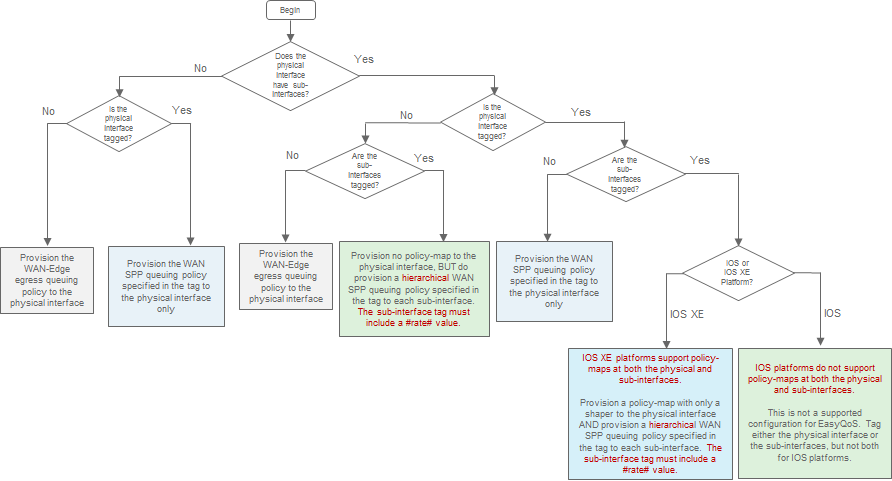
There are seven outcomes for provisioning the egress queuing policy in the figure above. Each is discussed below.
- Note: Bandwidth allocations within custom Queuing Profiles do not apply to physical interfaces or logical sub-interfaces considered to be connected to a service provider managed service. However, DSCP markings within custom Queuing Profiles are provisioned within the ingress classification & marking policy applied to physical interfaces or logical sub-interfaces considered to be connected to a service provider managed service.
No Sub-Interfaces, Physical Interface Not Tagged
If the physical interface does not have any logical sub-interfaces defined under it, and the physical interface is not configured with a SP Profile tag—EasyQoS will provision the WAN-Edge egress queuing policy to the physical interface. In this configuration, the physical interface is not considered to be connected to a service provider–managed service. Therefore, the WAN-Edge egress queuing policy discussed in the WAN-Edge Queuing Policy section of the *WAN and Branch Static QoS Design* chapter is applied to the physical interface. This is the same behavior as in APIC-EM release 1.3. Because EasyQoS does not consider the physical interface to be connected to a service provider managed WAN service, any custom Queuing Profiles, discussed in the Custom Queuing Profiles section of the *WAN and Branch Static QoS Design* chapter could also apply to the interface.
The ingress classification & marking policy—if applied—is also applied to the physical interface. Table 3 in the EasyQoS Policy Based on Platform, NBAR2 Protocol Pack, and Licensing section of the *WAN and Branch Static QoS Design* chapter discusses when an ingress classification & marking policy is applied to ISR and ASR router platforms.
No Sub-Interfaces, Physical Interface Tagged
If the physical interface does not have any logical sub-interfaces defined under it, and the physical interface is configured with a SP Profile tag, EasyQoS will provision an egress queuing policy (based on the SP Profile name in the tag) to the physical interface. In this configuration, the physical interface is considered to be connected to a service provider managed service. Therefore, the egress queuing policy specified by the SP Profile name within the tag (either a Custom SP Profile or one of the four default SP Profiles) is applied to the physical interface. This is the same behavior as in APIC-EM release 1.3.
The ingress classification & marking policy—if applied—is also applied to the physical interface. Table 3 in the EasyQoS Policy Based on Platform, NBAR2 Protocol Pack, and Licensing section of the *WAN and Branch Static QoS Design* chapter discusses when an ingress classification & marking policy is applied to ISR and ASR router platforms.
Sub-Interfaces, Physical Interface Not Tagged, Sub-Interfaces Not Tagged
If the physical interface has one or more logical sub-interfaces defined under it, but neither the physical interface nor the logical sub-interfaces are configured with a SP Profile tag, EasyQoS will provision the WAN-Edge egress queuing policy to the physical interface only. In this configuration, the physical interface and logical sub-interfaces are not considered to be connected to a service provider managed service. Therefore, the WAN-Edge egress queuing policy discussed in the WAN-Edge Queuing Policy section of the *WAN and Branch Static QoS Design* chapter is applied only to the physical interface. Because EasyQoS does not consider the physical interface and logical sub-interfaces to be connected to a service provider managed WAN service, any custom Queuing Profiles, discussed in the *Advanced Settings* section of the *APIC-EM and the EasyQoS Application* chapter could also apply to the physical interface. No egress queuing policies will be provisioned to the logical sub-interfaces. This is the same behavior as in APIC-EM release 1.3.
The ingress classification & marking policy—if applied—is also applied to the physical interface only. An ingress classification & marking policy applied to a physical interface also applies to traffic on its sub-interfaces. Table 3 in the EasyQoS Policy Based on Platform, NBAR2 Protocol Pack, and Licensing section the *WAN and Branch Static QoS Design* chapter discusses when an ingress classification & marking policy is applied to ISR and ASR router platforms.
The following provides an example of this configuration.
!
interface GigabitEthernet0/0/4
description APIC-EM-1.4-TEST
service-policy input prm-MARKING_IN
service-policy output prm-dscp#QUEUING_OUT
!
interface GigabitEthernet0/0/4.100
description APIC-EM-1.4-TEST
!
interface GigabitEthernet0/0/4.200
description APIC-EM-1.4-TEST
!
Sub-Interfaces, Physical Interface Not Tagged, Sub-Interfaces Tagged
If the physical interface has one or more logical sub-interfaces defined under it, and the physical interface is not configured with a SP Profile tag, but the logical sub-interfaces are configured with a SP Profile tag, EasyQoS will provision an egress queuing policy (based on the SP Profile name within the tag) to the logical sub-interfaces. In this configuration, the physical interface and logical sub-interfaces are considered to be connected to a service provider–managed service. Therefore, the egress queuing policy specified by the SP Profile name within the tag (either a Custom SP Profile or one of the four default SP Profiles) is applied to the logical sub-interfaces.
The SP Profile tag must include a #rate# field. The logical sub-interface egress queuing policy must be a hierarchical policy, in order for the ASR or ISR router to accept the service-policy statement. Otherwise, the router will generate an error such as “CBWFW: Not supported on sub-interface”. Therefore the #rate# field of the SP Profile tag must be included within the logical sub-interface description.
- Note: The SP Profile tags defined within logical sub-interface descriptions under the same physical sub-interface must all specify the same SP Profile name (either a Custom SP Profile name or one of the four default SP Profile names). For example, specifying an SPP-4Class model and an SPP-8Class module on two logical sub-interfaces under the same physical interface is not a supported configuration. However, the values of the #rate# field can be different for each sub-interface. Because of this restriction, if one logical sub-interface under a physical interface has a SP Profile tag configured, then all logical sub-interfaces under the same physical interface must have SP Profile tags configured.
The ingress classification & marking policy—if applied—is applied to each logical sub-interface. Although an ingress classification & marking policy applied to a physical interface also applies to traffic on its sub-interfaces, applying the ingress classification & marking policy to individual sub-interfaces may provide more granular visibility into traffic on each sub-interface. Table 3 in the EasyQoS Policy Based on Platform, NBAR2 Protocol Pack, and Licensing section the *WAN and Branch Static QoS Design* chapter discusses when an ingress classification & marking policy is applied to ISR and ASR router platforms.
The following provides a simplified example of this configuration.
!
interface GigabitEthernet0/0/2
description APIC-EM-1.4-TEST
!
interface GigabitEthernet0/0/2.100
description APIC-EM-1.4-TEST #WAN#60M#SPP1#
service-policy input prm-MARKING_IN
service-policy output prm-dscp#EQ_1#shape#60.0
!
interface GigabitEthernet0/0/2.200
description APIC-EM-1.4-TEST #WAN#15M#SPP1#
service-policy input prm-MARKING_IN
service-policy output prm-dscp#EQ_1#shape#15.0
!
Sub-Interfaces, Physical Interface Tagged, Sub-Interfaces Not Tagged
If the physical interface has one or more logical sub-interfaces defined under it, and the physical interface is configured with a SP Profile tag, but the logical sub-interfaces are not configured with SP Profile tags—EasyQoS will provision an egress queuing policy (based on the SP Profile name within the tag) to the physical interface only. In this configuration, the physical interface and logical sub-interfaces are considered to be connected to a service provider managed service. Therefore, the egress queuing policy specified by the SP Profile name within the tag (either a Custom SP Profile or one of the four default SP Profiles) is applied to the physical interface.
- Note: If one logical sub-interface under a physical interface has a SP Profile tag configured, then all logical sub-interfaces under the same physical interface must have SP Profile tags configured. Defining some logical sub-interfaces with SP Profile tags and other logical sub-interfaces without SP Profile tags under the same physical interface is not a supported configuration.
The ingress classification & marking policy—if applied—is applied to the physical interface only. An ingress classification & marking policy applied to a physical interface also applies to traffic on its sub-interfaces. Table 3 in the EasyQoS Policy Based on Platform, NBAR2 Protocol Pack, and Licensing section the *WAN and Branch Static QoS Design* chapter discusses when an ingress classification & marking policy is applied to ISR and ASR router platforms.
The following provides a simplified example of this configuration.
!
interface GigabitEthernet0/0/5
description APIC-EM-1.4-TEST #WAN#50M#SPP:SPP2-5Class#
service-policy input prm-MARKING_IN
service-policy output prm-dscp#EQ_SPP2-5Class#shape#50.0
!
interface GigabitEthernet0/0/5.100
!
interface GigabitEthernet0/0/5.200
!
Sub-Interfaces, Physical Interface Tagged, Sub-Interfaces Tagged, IOS XE Device
If the physical interface has one or more logical sub-interfaces defined under it, and both the physical interface and logical sub-interfaces are configured with SP Profile tags, and the device is an IOS XE router, EasyQoS will provision a more complex egress queuing policy. IOS XE routers include the ASR 1000 Series and the ISR 4000 Series. In this configuration, the physical interface and logical sub-interfaces are considered to be connected to a service provider managed service.
At the physical interface, EasyQoS will provision a non-hierarchical policy-map with only a shaper. A simplified example of the provisioning of the physical interface by EasyQoS is shown below.
!
policy-map prm-interface-shaper#Gig0/0/4
class class-default
shape average 100000000
!
~
!
interface GigabitEthernet0/0/4
description APIC-EM-1.4-TEST #WAN#100M#SPP:SPP4-8Class#
service-policy output prm-interface-shaper#Gig0/0/4
!
The name of the policy-map will include the physical interface name in order for the network operator to more easily identify it within the router configuration.
SP Profile tag configured within the physical interface description must include all three fields - #WAN#, #rate#, and #SP_Profile_Name#. The #rate# field is used to determine the shaper average value within the policy-map of the physical interface. Although the SP Profile name is configured within the physical interface—IOS XE devices do not allow a hierarchical policy-map to be applied at both the physical interface and logical sub-interfaces. Only a shaper is allowed at the physical interface in this configuration.
- Note: The SP Profile name in the tag (either a Custom SP Profile or one of the four default SP Profiles) configured within the description of the physical interface must be the same as the SP Profile names configured in the descriptions of each of the logical sub-interfaces. For example, specifying an SPP-8Class model at the physical interface and an SPP-5Class model on one or more of the logical sub-interfaces under the same physical interface is not a supported configuration. However, the values of the #rate# field can be different for the physical interface and for each logical sub-interface.
At each logical sub-interface, EasyQoS will provision an egress queuing policy (based on the SP Profile name within the tag) to the logical sub-interfaces. Therefore, the egress queuing policy specified by the SP Profile name within the tag (either a Custom SP Profile or one of the four default SP Profiles) is applied to the logical sub-interfaces.
The SP Profile tag must include a #rate# field. The logical sub-interface egress queuing policy must be a hierarchical policy, in order for the router to accept the service-policy statement. Otherwise, the router will generate an error such as “CBWFW: Not supported on sub-interface”. Therefore the #rate# field of the SP Profile tag must be included within the logical sub-interface description.
- Note: If one logical sub-interface under a physical interface has a SP Profile tag configured, then all logical sub-interfaces under the same physical interface must have SP Profile tags configured. Defining some logical sub-interfaces with SP Profile tags and other logical sub-interfaces without SP Profile tags under the same physical interface is not a supported configuration.
A simplified example of the provisioning of the sub-interfaces by EasyQoS is shown below.
!
interface GigabitEthernet0/0/4.100
description APIC-EM-1.4-TEST #WAN#20M#SPP:SPP4-8Class#
service-policy input prm-MARKING_IN
service-policy output prm-dscp#EQ_SPP4-8Class#shape#20.0
!
interface GigabitEthernet0/0/4.200
description APIC-EM-1.4-TEST #WAN#10M#SPP:SPP4-8Class#
service-policy input prm-MARKING_IN
service-policy output prm-dscp#EQ_SPP4-8Class#shape#10.0
!
The ingress classification & marking policy—if applied—is applied to each logical sub-interface. Although an ingress classification & marking policy applied to a physical interface also applies to traffic on its sub-interfaces, applying the ingress classification & marking policy to individual sub-interfaces may provide more granular visibility into traffic on each sub-interface. Table 3 in the EasyQoS Policy Based on Platform, NBAR2 Protocol Pack, and Licensing section the *WAN and Branch Static QoS Design* chapter discusses when an ingress classification & marking policy is applied to ISR and ASR router platforms.
Sub-Interfaces, Physical Interface Tagged, Sub-Interfaces Tagged, IOS Device
IOS routers—which include the ISR G2 3900 and 2900 Series and the ISR 800 Series—do not support policy-maps configured at both the physical interface and logical sub-interfaces. Therefore, configuring a WAN SPP tag at both a physical interface and its sub-interfaces is not a valid configuration supported by EasyQoS for IOS routers. An error will be generated, and the QoS policy will fail for the IOS router if the network operator has tagged both a physical interface and its sub-interfaces. The network operator should modify the configuration on the IOS router so that only the physical interface is tagged or only its sub-interfaces are tagged. The resulting QoS policy provisioned to the WAN interface, based upon whether the physical interface is tagged, or the sub-interfaces are tagged, was discussed in previous sections.
Server IP/Port-Based Custom Applications and Managed Service WANs
Custom applications based on server IP addresses and/or ports do not pass through the NBAR engine within an ASR or ISR router platform. As discussed in the *Custom Applications on ASR and ISR Platforms* section in the *Branch and WAN Static QoS Design* chapter, port-based Custom applications are provisioned under one of the 11 new class-map entries that include the word “CUSTOM”—based on the traffic-class to which the port-based Custom application belongs. This is a new behavior, as of APIC-EM release 1.4 and higher.
In APIC-EM release 1.3 port-based Custom applications were added to the prm-MARKING_IN#TUNNELED-NBAR traffic-class in ASR and ISR router platforms by EasyQoS. Prior to APIC-EM release 1.3 Custom applications were configured as NBAR applications. No action is specified for the prm-MARKING_IN#TUNNELED-NBAR traffic class within the ingress classification & marking policy on ASR and ISR router platforms. When traffic from such a Custom application exits the organization’s network, entering a service provider managed-service network, the Custom application traffic may be remarked to match the allowed DSCP markings for the service provider traffic-class to which the Custom application is mapped.
With APIC-EM release 1.3, when the Custom application traffic re-enters the organization’s network at the other end of service provider manage-service network, the traffic would not be remarked back to its original DSCP marking. Instead, port-based Custom applications would retain the DSCP markings to which they were mapped when entering the service provider managed-service network. APIC-EM release 1.4 and higher modifies this behavior. Traffic re-entering the organization’s network at the other end of the service provider managed-service network is now classified to one of the 11 new class-map entries that include the word “CUSTOM”—based on the traffic-class to which the port-based Custom application belongs. Therefore traffic from port-based Custom applications is now remarked back to its original DSCP marking.