Chapter 11: Dynamic Qos Design
For the APIC-EM 1.6 release, Dynamic QoS is still a Beta application.
Need for Dynamic QoS
Current methods of discovering voice and video endpoints rely upon the use of protocols such as Cisco CDP, in order for the device to identify itself to the access-edge (that is, switch port) of the network. However two issues exist with regard to the use of CDP:
- CDP is not a secure protocol. CDP does not rely upon any mechanism for the endpoint device to authenticate with the network or for the network to authenticate to the endpoint device. Hence, anyone with some knowledge of programming could write an application allowing any device to “spoof” the access-edge network device (that is, switch) into thinking that the endpoint device is a Cisco IP phone or Cisco video conferencing endpoint.
- Mobile devices (such as smart phones and tablets), laptops, and PCs—running voice and video applications such as Cisco Jabber—typically do not use CDP to identify the device as being voice and/or video capable.
The APIC-EM EasyQoS solution discovers wired Cisco IP phones, Cisco IP video conferencing endpoints, Cisco TelePresence endpoints, and Cisco IP video surveillance cameras through the use of CDP. For wired devices, EasyQoS uses the IP addresses of the hardware endpoints collected through CDP information, along with the knowledge of which Catalyst switch and switch port the endpoint is connected to—in order to pre-populate ACE entries within classification & marking ACLs for Static QoS on switching devices. Because the wireless classification & marking policy deployed by EasyQoS relies on an AVC/NBAR profile, no equivalent ACE or ACL entries are generated for wireless devices. Wired devices with voice & video applications that do not use CDP also have no ACE entries generated within classification & marking ACLs for Static QoS on switching devices.
Dynamic QoS is designed to address these devices, as well as to provide a more authoritative source of information regarding whether flows should be allowed onto the network with voice and video markings, rather than simply trusting CDP information that can be easily spoofed.
Dynamic QoS Operation
For Dynamic QoS, a REST-based API has been implemented within APIC-EM. This API allows a call signaling device, such as CUCM, to inform APIC-EM EasyQoS when a voice and/or video call is established, and also when the voice and/or video call is terminated. Dynamic QoS applies to Catalyst switches (wired) currently.
Dynamic QoS for Wired Devices
Dynamic QoS for wired devices affects the ingress classification & marking policy of both access-layer switches and the distribution-layer switches to which those access-layer switches are connected.
APIC-EM EasyQoS Pre-Configuration for Access-Layer Switches
When Dynamic QoS is first enabled within EasyQoS—but before any voice and/or video calls are placed—APIC-EM will create class-map and policy-map shells for each switch port on every switch configured with the role of an access-layer switch within the policy scope. An example of the class-map shells and policy-map shells for one switch port is shown below.
!
class-map match-any prm-DYN-Gig1/0/13#DYN_VOICE
match access-group name prm-DYN-Gig1/0/13#DYN_VOICE__acl
class-map match-any prm-DYN-Gig1/0/13#DYN_VIDEO
match access-group name prm-DYN-Gig1/0/13#DYN_VIDEO__acl
class-map match-any prm-DYN-Gig1/0/13#DYN_REALTIME
!
policy-map prm-DYN-Gig1/0/13
class prm-DYN-Gig1/0/13#DYN_VOICE
set dscp ef
class prm-DYN-Gig1/0/13#DYN_REALTIME
set dscp cs4
class prm-DYN-Gig1/0/13#DYN_VIDEO
set dscp af41
class class-default
set dscp default
!
ip access-list extended prm-DYN-Gig1/0/13#DYN_VIDEO__acl
ip access-list extended prm-DYN-Gig1/0/13#DYN_VOICE__acl
!
The policy-maps have entries for voice, video, and real-time (that is, TelePresence) devices. Only voice and video class-map entries are currently used for Dynamic QoS by EasyQoS. The policy-map actions for each of the class-maps is to set the marking of the media to DSCP values that are consistent with those set for voice and video media by Static QoS.
Empty ACLs are created for dynamic voice and video calls. These are dynamically populated by ACE entries based on information passed to APIC-EM by call signaling platforms such as CUCM, via the northbound REST-based API.
APIC-EM EasyQoS Pre-Configuration for Distribution-Layer Switches
With APIC-EM release 1.5 and higher, only when the network operator has chosen to implement Dynamic QoS will the EasyQoS application additionally create and apply an ingress classification & marking policy to all uplink ports that connect to access-layer switches. This classification & marking policy is similar, but not identical, to the ingress classification & marking policy applied to switch ports connected to devices (access-edge switch ports) on switches functioning in the role of an access-layer switch within APIC-EM.
APIC-EM will create class-maps and policy-maps on every switch configured in the role of a distribution-layer switch within the policy scope. An example of the class-maps configured by EasyQoS are shown below.
!
class-map match-any prm-APIC_QOS_IN#CONTROL
match access-group name prm-APIC_QOS_IN#CONTROL__acl
match dscp cs6
class-map match-any prm-APIC_QOS_IN#VOICE
match access-group name prm-APIC_QOS_IN#VOICE__acl
match dscp ef
class-map match-any prm-APIC_QOS_IN#BROADCAST
match access-group name prm-APIC_QOS_IN#BROADCAST__acl
match dscp cs5
class-map match-any prm-APIC_QOS_IN#REALTIME
match access-group name prm-APIC_QOS_IN#REALTIME__acl
match dscp cs4
class-map match-any prm-APIC_QOS_IN#MM_CONF
match access-group name prm-APIC_QOS_IN#MM_CONF__acl
match dscp af41
class-map match-any prm-APIC_QOS_IN#MM_STREAM
match access-group name prm-APIC_QOS_IN#MM_STREAM__acl
class-map match-any prm-APIC_QOS_IN#SIGNALING
match access-group name prm-APIC_QOS_IN#SIGNALING__acl
class-map match-any prm-APIC_QOS_IN#OAM
match access-group name prm-APIC_QOS_IN#OAM__acl
class-map match-any prm-APIC_QOS_IN#TRANS_DATA
match access-group name prm-APIC_QOS_IN#TRANS_DATA__acl
class-map match-any prm-APIC_QOS_IN#BULK_DATA
match access-group name prm-APIC_QOS_IN#BULK_DATA__acl
class-map match-any prm-APIC_QOS_IN#SCAVENGER
match access-group name prm-APIC_QOS_IN#SCAVENGER__acl
class-map match-any prm-APIC_QOS_IN#TUNNELED
match access-group name prm-APIC_QOS_IN#TUNNELED__acl
!
With Dynamic QoS, policy-maps dynamically applied to access-edge switch ports classify and mark voice and video traffic based on signaling from CUCM. The marking of this traffic must be preserved as it enters the distribution-layer switch. Therefore, the distribution-layer policy contains the following additions:
- The class-map definition for prm-APIC_QOS_IN#VOICE also contains a “match dscp ef” entry.
- The class-map definition for prm-APIC_QOS_IN#MM_CONF also contains a “match dscp af41” entry.
- The class-map definition for prm-APIC_QOS_IN#REALTIME also contains a “match dscp cs4” entry.
- The class-map definition for prm-APIC_QOS_IN#BROADCAST also contains a “match dscp cs5” entry.
- A class-map definition for control traffic (prm-APIC_QOS_IN#CONTROL) that matches on both an ACL and on DSCP markings (cs6) to preserve markings from the access-layer switches is also included.
All other class-maps match on just ACLs. An example of the policy-map configured by EasyQoS for distribution-layer switches is shown below.
!
policy-map prm-APIC_QOS_IN
class prm-APIC_QOS_IN#VOICE
set dscp ef
class prm-APIC_QOS_IN#BROADCAST
set dscp cs5
class prm-APIC_QOS_IN#REALTIME
set dscp cs4
class prm-APIC_QOS_IN#MM_CONF
set dscp af41
class prm-APIC_QOS_IN#MM_STREAM
set dscp af31
class prm-APIC_QOS_IN#SIGNALING
set dscp cs3
class APIC_EM-CONTROL
set dscp cs6
class prm-APIC_QOS_IN#OAM
set dscp cs2
class prm-APIC_QOS_IN#TRANS_DATA
set dscp af21
class prm-APIC_QOS_IN#BULK_DATA
set dscp af11
class prm-APIC_QOS_IN#SCAVENGER
set dscp cs1
class prm-APIC_QOS_IN#TUNNELED
class class-default
set dscp default
!
The policy-map at the distribution-layer switch also includes a class-map entry for control traffic. Control traffic may be generated by the access-layer switch and sent to the distribution-layer switch or generated by any Access-Points connected to an access-layer switch and sent to the distribution-layer switch.
The ACLs for the distribution-layer ingress classification & marking policy provisioned by EasyQoS to Catalyst switching platforms are basically the same as the ACLs provisioned by EasyQoS to Catalyst switching platforms—when configured in the role of an access-layer switch. These were discussed in the *Access-Control Lists* section of the *Campus LAN Static QoS Design* chapter and will not be repeated here.
The service-policy is applied to all distribution-layer switch ports that connect to access-layer switches. An example of the configuration provisioned by EasyQoS is shown below.
!
interface TenGigabitEthernet1/0/1
service-policy input prm-APIC_QOS_IN
!
APIC-EM EasyQoS does not apply the service-policy to distribution-layer switch ports that connect to other distribution-layer switches or to core-layer switches.
Wired Dynamic QoS Workflow
After all of the pre-configuration has been completed by APIC-EM EasyQoS, Dynamic QoS is ready to accept signaling for voice/video calls via the REST-based API from call signaling agents, such as CUCM. The following figure provides a high-level overview of how Dynamic QoS operates for wired devices, when setting-up a call.
- Dynamic QoS—Wired Voice/Video Call Proceeding
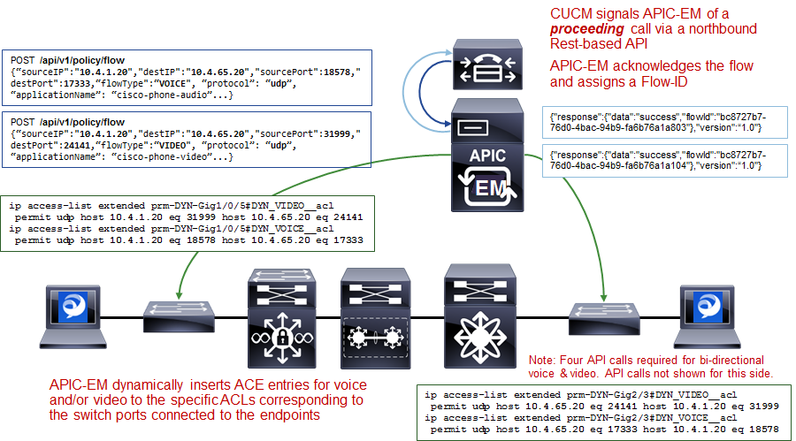
As shown in the figure above, call signaling agents such as CUCM signal to APIC-EM of a proceeding call via a northbound REST-based API. The information within the REST-based API call includes the source and destination IP addresses, the protocol (UDP), the media ports, and the type of media—VOICE or VIDEO. CUCM functions as a SIP back-to-back user-agent, meaning all SIP call signaling is between the endpoint and CUCM. Hence, CUCM has visibility into all call setup and call teardown signaling. Further, CUCM actually assigns the media ports that are used for the voice and video media sent between the endpoints. For a voice only call, one API call for audio media is needed for each side. A total of two API calls is needed for a bi-directional audio call. For a voice and video call, two API calls—one for audio media and one for video media is needed for each side. A total of four API calls is needed for a bi-directional voice and video call. APIC-EM will acknowledge each API call and will assign a flow identifier for each flow. The flow identifier is used to identify the flow during the teardown of the call.
APIC-EM then uses its southbound APIs (CLI) to dynamically insert ACE entries for the voice and/or video IP addresses and media into the specific ACLs corresponding to the switch ports connected to the endpoints. The following provides an example of the configuration provisioned by EasyQoS that populates the ACE entries within the dynamic voice and video ACLs.
!
ip access-list extended prm-DYN-Gig1/0/5#DYN_VIDEO__acl
permit udp host 10.4.1.20 eq 31999 host 10.4.65.20 eq 24141
ip access-list extended prm-DYN-Gig1/0/5#DYN_VOICE__acl
permit udp host 10.4.1.20 eq 18578 host 10.4.65.20 eq 17333
!
The ACLs are port-specific. The *Endpoints Running Cisco Jabber Soft Clients* section below, discusses how APIC-EM learns to which switch and switch port endpoint devices are connected.
Finally, APIC-EM EasyQoS APIC-EM EasyQoS dynamically swaps the Static QoS ingress classification & marking service-policy on the switch ports connected to the endpoints, to the service-policy used for Dynamic QoS. An example of the configuration provisioned by EasyQoS is shown below.
!
interface GigabitEthernet1/0/5
no service-policy input prm-APIC_QOS_IN
service-policy input prm-DYN-Gig1/0/5
!
This is the reason for the existence of the ingress classification & marking policy applied to distribution-layer switch ports connected to access-layer switches, when Dynamic QoS is enabled. When the Static QoS ingress classification & marking service-policy is replaced with the dynamic ingress classification & marking service-policy, only voice and video media are matched for that particular switch port, at the access-layer switch. The distribution-layer ingress classification & marking policy, applied by APIC-EM when EasyQoS is first enabled, is used to classify and mark all other applications that may still be sent by the endpoint device connected to the switch port. The distribution-layer ingress classification & marking policy is technically applied to all traffic from the access-layer switch. However, the policy is essentially a superset of the Static QoS policy, hence applications from the other switch ports on the access-layer switch will not be affected, because they are already marked correctly.
The following figure provides a high-level overview of how Dynamic QoS operates for wired devices, when tearing-down a call.
- Dynamic QoS—Wired Voice/Video Call Termination
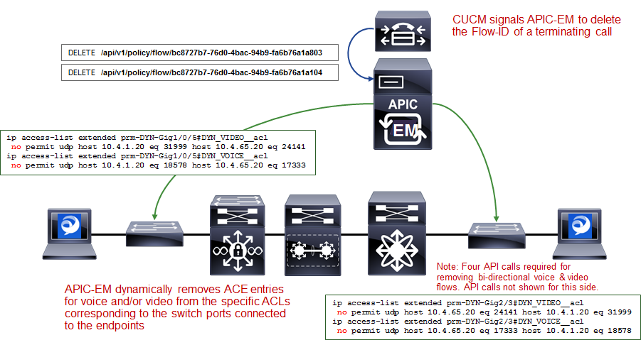
As can be seen in the figure above, CUCM signals to APIC-EM via the REST-based API that the call has terminated. For calls with voice and video media flows, two API calls may be sent by CUCM for each side, for a total of four API calls per bi-directional voice and video call.
APIC-EM EasyQoS will then dynamically swap the ingress classification & marking service-policy on the switch ports connected to the endpoints, back to the service-policy used for Static QoS. An example of this is shown below.
!
interface GigabitEthernet1/0/5
no service-policy input prm-DYN-Gig1/0/5
service-policy input prm-APIC_QOS_IN
!
Finally, APIC-EM EasyQoS dynamically removes ACE entries from the dynamic ACLs, based on CUCM signaling.
!
ip access-list extended prm-DYN-Gig1/0/5#DYN_VIDEO__acl
no permit udp host 10.4.1.20 eq 31999 host 10.4.65.20 eq 24141
ip access-list extended prm-DYN-Gig1/0/5#DYN_VOICE__acl
no permit udp host 10.4.1.20 eq 18578 host 10.4.65.20 eq 17333
!
Endpoints Running Cisco Jabber Soft Clients
Cisco Jabber soft clients are also discovered by APIC-EM and populated within Dynamic QoS ACLs. However, Cisco Jabber soft clients do not typically send CDP information. Instead, Cisco IP Device Tracking (IPDT) must be enabled on Catalyst switches in order to support the ability for APIC-EM to discover and populate devices with Cisco Jabber soft clients.
- Note: Devices running the Cisco Medianet Services Interface (MSI) may generate CDP information. However, the MSI interface is only supported on Windows 7 & 8, and Mac OS X 10.7 and 10.8 platforms, and no further development is expected for the MSI.
For a Catalyst 3850/3650 Series switch, IPDT is enabled via the following interface-level configuration command.
!
ip device tracking maximum x
!
“X” is the maximum number of devices to be tracked on the interfaces. The values range from 0 to 63,535 devices. A value of 0 disables IP device tracking on the switch port.
IPDT causes the switch port to send Address Resolution Protocol (ARP) probes (ARP request packets) periodically. The interval between ARP probes can be controlled via the following interface-level configuration command.
!
ip device tracking probe interval x
!
“X” is the interval between which ARP probes are sent. The default value is 30 seconds.
The number of ARP probes sent per interval can also be controlled via the following interface-level configuration command.
!
ip device tracking probe count x
!
“X” is the number of ARP probes sent per interval. The default value is 3 probes.
At a global configuration level, the following command can be used to delay the switch port from sending the ARP probes after a link up event or link flap (link down/link up).
!
ip device tracking probe delay 10
!
This command can be used to prevent the switch from sending an ARP probe while the device connected to the switch port checks for duplicate IP addresses.
As a prerequisite for supporting the ability for APIC-EM to dynamically discover adds/moves/changes of hardware endpoint devices and automatically update ACL entries for these devices, the network operator will need to enable SNMP traps (particularly the link up/link down trap) on access-layer switches to be sent to APIC-EM.
After the switch port connected to a hardware endpoint goes up/down, APIC-EM will receive an SNMP trap. APIC-EM will start collecting information from the access-layer switch that generated the SNMP trap, about the new endpoints. This will take approximately 80 seconds, plus the time needed for the collection of the device information.